UP-67M4, UP-127M4,
UP-247M2, UP-487
Modular amplifiers. v 2.3
Modular
amplifiers
9
(12)
PRIORITY CHANNEL AND (13) PROGRAM CHANNEL
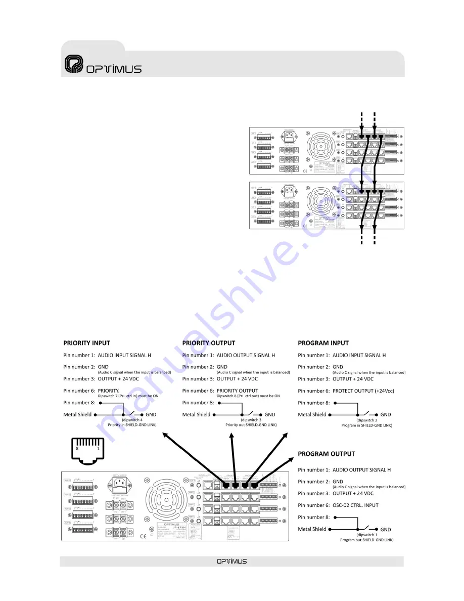
The two input channels (PROGRAM & PRIORITY) from
each amplifier use 4 RJ45 type connectors in parallel
2 to 2.
This way, they can provide signal to other power
units (see figure 9).
For the connection, you must use FTP Cat 5 cable,
which main feature is that it has very low impedance,
which allows to have an exceptionally flat frequency
response even for long distances, and to comply with
the CMRR & Crosstalk features required for the
analogical audio systems.
The signal inputs have a sensitivity of 0 dBu (775
mV). The pin number 3 provides a 24 V.d.c. voltage
which can be used to supply devices of low
consumption. The maximum intensity supplied is of
200 mA. in each channel.
In the PRIORITY channel, when joining the pin
number 6 to the pin number 8, the priority system is
activated as well as the security paging auxiliary
relay (DIP switch 7
Pri. ctrl in
must be ON).
It is possible to transmit the priority control to other
power units through the pin nº 6 of the PRIORITY
OUTPUT connector (DIP switch 8
Pri. ctrl out
must be
ON).
Figure 9
ATTENTION:
In order to link the program and priority audio signals
from one power stage to the other, without using
external cabling set the
Pro. audio bus
and
Pri. audio
bus
switch from AMP2, AMP3 and AMP4 in ON. In
AMP1 they must be in OFF.
To link different mainframes, it can only be used the
outputs from AMP1.
Figure 10


