UP120M4 AMPLIFIER
UP120M4
17
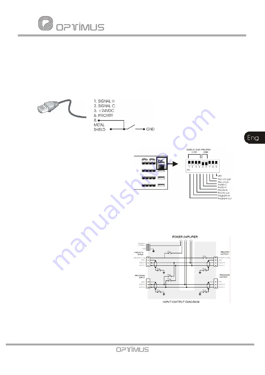
The signal inputs are
balanced
by transformer and have a sensitivity of
0 dBu
(775mV). The
pin n.º 3 provides a 24 Vdc voltage which can be used to supply devices of low consumption.
The maximum intensity supplied is of 200 mA in each channel.
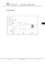
In the PRIORITY channel, when joining the pin º 6 to the pin nº 8, the priority system is
activated as well as the security paging auxiliary relay. It is possible to transmit the priority
control to other power units through the pin nº 6 of the PRIORITY OUTPUT connector, always
depending on the position of the dipswitches 7 & 8 (see section 3. REAR VIEW, nº 9).
12) DIPSWITCH.
SHIELD - GND LINK. (dipswitches nº 1, 2, 3
& 4).
These 4 dipswitches allow removing the cable
shielding from the internal ground of the
equipment for each one of the RJ-45
connectors. Normally they are in ON position
(shielding and ground joined). To separate the
same, place the corresponding dipswitch in
OFF position.
PRI-PRO LINK (dipswitches nº 5 & 6).
These two dipswitches join internally the H audio signal and the C audio signal (when the input
is balanced) that are in the PRIORITY OUTPUT with the PROGRAM INPUT. Normally they are
in OFF position (separated audio signals). To join the same, place the corresponding dipswitch
in ON position.
PRIORITY CONTROL IN (dipswitch nº 7).
In OFF position, it disables the priority contact
of the RJ PRIORITY INPUT connector.
PRIORITY CONTROL OUT (dipswitch nº 8).
In OFF position, it disables the priority contact
of the RJ PRIORITY OUTPUT connector.
JPA (dipswitch nº 9).
Put OFF when the equipment includes the
oscillators.
Fig. 7
Fig. 8a
Fig. 8b


