User Manual – ePX 200
OptiPro Systems, LLC.
Page 28 of 60
Last Modified: 7/30/2014
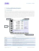
7.2
Jump To…
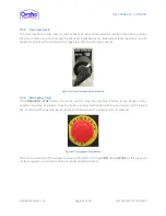
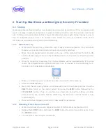
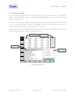
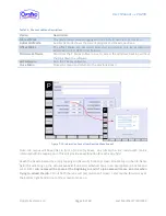
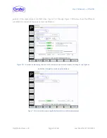
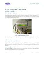
The [JUMP TO…]
button, from any screen, allows quick navigation to Job Setup, True Tool, and Polish
Setup menus.
Figure 7-2
: “JUMP TO…” buttons activated for quick navigation
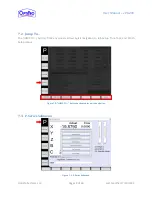
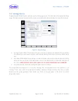
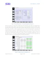
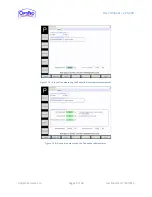
7.3
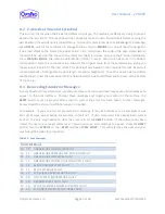
P-Series Submenu
Figure 7-3: P-Series Submenu


