User Manual – ePX 200
OptiPro Systems, LLC.
Page 36 of 60
Last Modified: 7/30/2014
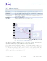
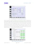
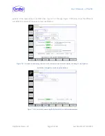
The Polishing Program Setup screen is the third screen in the new job setup sequence. This screen
consists of four independent polishing programs. Each program can be run individually or chained
together by toggling the checkbox under [Enable Cycle]. The grayed out boxes contain data that is
calculated based on the values that are entered in the other fields and cannot be interacted with. Many
of the fields such as Stroke Distance, Oscillations per Minute, and Bladder Pressure will be tweaked by
the technician as he or she gains experience. Most customers will do a runoff with a part they are
currently making at OptiPro prior to machine delivery. This provides an opportunity for OptiPro to fully
develop the tool set and tweak the process to the customer’s specifications. The two day training that
takes place during install sets a good baseline for the technician to follow for future jobs. The numbers
entered in the Stroke Distance, Oscillations per Minute, Bladder Pressure, Tool Speed and Speed Factor
in Figure 7-13 above are generally a safe place to start. OptiPro recommends one general guideline:
stroke distances beyond 3.00 mm are unnecessarily large and generally won’t help with figure
correction.
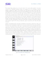
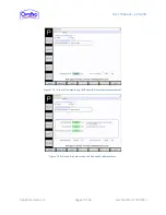
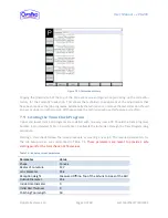
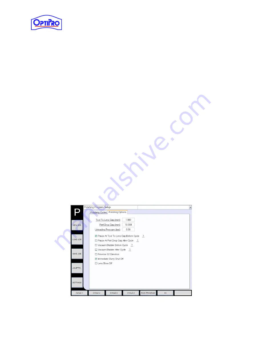
Tapping on the Polishing Options tab opens up the Options screen as seen in Figure 7-15. There is one
field in particular that is extremely important and cannot be overlooked. The [Tool to Lens Gap] field is
one of the most important fields in the software. A properly set tool to lens gap will ensure very good
quality optics. If the gap is set improperly, the quality of the finished optic will suffer and could even
increase the chance of a machine crash. The general rule of thumb with a new job is to set the gap at 1-
2mm and make sure the [Pause at tool to lens gap before cycle] checkbox is checked. These two actions
allow the technician to check the gap before the spindles start. The general rule of thumb here, the lens
should move about half of the sidewall thickness. Activating the bladder by stepping on the foot
activation switch will allow the technician to view the gap between the polisher and the lens. The
unloading pressure, which is usually set to 1 bar, provides air pressure when the foot switch is activated.
Figure 7-14: Job Menu Screen 3, Polishing Options

