17
4. Assembling and Operation of Fluorescence Illuminator A12.0910
4-1 Assemblage Steps
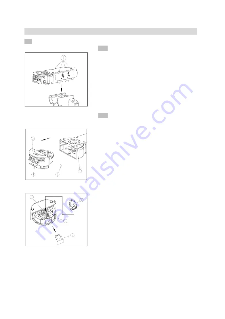
4-1-1 Assemble the Fluorescence Illuminator
(1) Withstand the gap of the cap
①
on the illuminator
with a small pointed tool, to take off the cap
①
. (See
Fig. 28)
(2) Put the illuminator into the body along with the
rounded side, then push it toward the light source
direction, to make the epi-illuminator posted flat with
the body.
(3) Tighten the four M5 hexagon screws in the
illuminator with the spanner, then cover back the cap.
4-1-2 Assemble the Fluorescence Filter Sets
(1) Loose the right side lock screw
①
of the turntable
fluorescence illuminator, with a M4 inner hexagon
spanner, and pull the front cover group
②
out of the
dovetail groove. (See Fig. 29)
(2) The blinker board
⑤
is installed in the fluorescence
filter group. When using the fluorescence filter group,
first loose the lock screw
⑥
with the inner hexagon
spanner, and take off the blinker board
⑤
. (See Fig. 30)
(3) Put the diaphragm slice of the fluorescence filter
group
⑦
which is to be assembled upward, and match
the dovetail groove of the fluorescence filter group
⑦
with the dovetail wedge of the front cover group
②
, and
push to the bottom. Tighten the lock screw
⑥
.
(4) Check the ID
⑧
on the dovetail interface, and insert
the nameplate
④
of the fluorescence filter group into the
interface
③
with the same number in front of the front
cover group
②
.
(5) Repeat the steps above, to assemble other
fluorescence filter groups into the turntable of the front
cover group
②
.
(6) Then match the dovetail wedge of the front cover
group
②
with the dovetail groove of the turntable
epi-illuminator, and push to the bottom. Tighten the lock
screw
①
.
Fig.30
Fig.29
Fig. 28


