13
4. Assembling and Operation of Accessories
EX31 Series
4-1
Assembling and Operation of the LED Fluorescence Device
4-1-1
Assembling and Operation of the LED
Fluorescence Illuminator
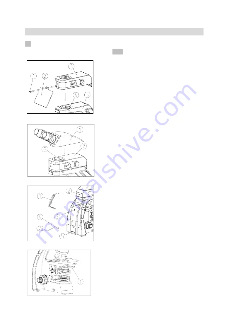
(1) Fix the light shield
②
on the LED
fluorescence illuminator
③
with the screw
①
.
(See Fig. 26)
(2) Put the LED fluorescence illuminator
③
on
the arm
⑤
, and fix it with the lock screw
④
by
the hexagon spanner.
★
Assemble the light shield
②
only when
observing in UV lighting.
(3) Put the binocular/ trinocular Head
①
on the
LED fluorescence illuminator
②
, and fix it with
the lock screw
③
by the hexagon spanner. (See
Fig. 27)
(4) Insert one end of the power cable
①
into the
power socket
②
of the LED fluorescence
illuminator back, and then insert the other end
into the power socket
③
of the microscope back,
and ensure them be connected well. (see Fig. 27)
(5) Insert one end of the external power adaptor
④
into the power socket
⑤
of the microscope
back, and then insert the other end into the power
supply socket, and ensure them be connected
well. (see Fig. 28)
★
Before connecting the external power
adaptor, firstly rotate the transmission power
switch
and
the
reflection
adjustment
knob(with switch) to “Off”(turn off).
(6) When observing the fluorescence slide, pull
the fluorescence flashboard
①
a bit left, it will
sound a “Dida” when moved to the fluorescence
observation position, and the transmission
illumination path is totally covered. (See Fig. 29)
★
For transmission illumination observation,
pull the fluorescence flashboard
①
to the
right
side,
to
make
the
transmission
illumination path completely get through.
(7) The LED fluorescence filter block adjustment
knob
①
can be rotated for 180° according to the
arrowhead
direction,
to
change
between
transmission brightfield and LED fluorescence.
Flourescence means fluorescence observation,
and Brightfield means brightfield observation.
(See Fig. 30)
Fig.29
Fig.26
Fig.28
Fig.27


