Table of Contents
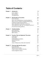
Chapter 1
Introduction
1-1
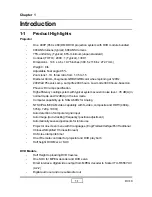
Product Highlight
1-1
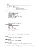
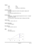
Mechanical Spec
1-2
Compatible Modes
1-9
Chapter 2
Disassembly of Procedure
2-1
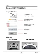
Equipment Needed
2-1
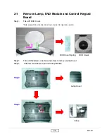
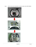
Remove Lamp, DVD Module and Control Keypad Board
2-2
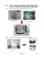
Remove Top Cover, Speaker, Keypad Board, Rear Cover,
Fan Module, Main Board and Audio Board
2-5
Remove Lamp Driver, LVPS, Engine, Color Wheel
2-8
Remove DMD Board, DMD Chip, Thermal Board,Front Cover,
Elevator Module and Keypad Board.
2-10
Chapter 3
Troubleshooting
3-1
Equipment Needed
3-1
LED Indications Table
3-1
Main Procedure
3-1
Chapter 4
Function Test and Alignment Procedure
4-1
Test Equipment
4-1
Test Condition
4-1
Test Display Modes and Pattern
4-2
Inspection Procedure
4-5
Calibration
4-7
Guide to Entering Service Mode and Factory Reset
4-8
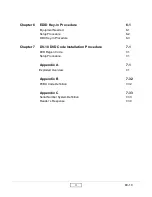
Chapter 5
Firmware Upgrade Procedure
5-1
Equipment Needed
5-1
Hardware Setup Procedure
5-1
Firmware Progarm Installation Procedure
5-2
Firmware Upgrade Procedure
5-9
DV-10
Summary of Contents for DV10 MovieTime
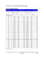
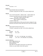
Page 9: ...DV 10 1 5 Throw Ratio 1 25 1 5 Projection Distance Image Width ...
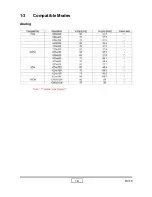
Page 13: ...DV 10 1 9 1 3 Compatible Modes Analog Note means compressed ...
Page 39: ...DV 10 5 4 4 Click Next button 1 2 5 Choose All icon then click Next button ...
Page 40: ...DV 10 5 5 6 Click Next button 7 The program is executing Initializing status ...
Page 57: ...DV 10 7 1 Appendix A Exploded Overview I DV 10 Unit ...
Page 59: ...DV 10 7 3 II Top Cover Module ...
Page 61: ...DV 10 7 5 III Engine Module ...
Page 64: ...DV 10 7 8 V Sub Engine Module ...
Page 69: ...DV 10 7 13 VIIII DVD Cover Module ...
Page 71: ...DV 10 7 15 X DVD Loader Module ...
Page 73: ...DV 10 7 17 XI Lamp Module ...
Page 75: ...DV 10 7 19 XII Engine Base ...

