奇
菱
光電股份有限公司
Chi Lin Optronics Corp.
Doc. No
CS-72601
Version A3
Title
CHT-726 Level 1 Service Manual
Page
57 / 75
8.6
Replace The Video Module, The I/O Board, The Ballast, The
Thermal Sensor, and The Power Module
This section will show the disassembly and assembly of the electronic system step by step. The
electronic part includes the keypad, the control board, the connection board, the video module, the I/O
board, the ballast, the thermal sensors and the power module. The adjustment on the video module
(charpter 8.7) is needed when the video module is replaced.
Note: 1. The front IR sensor is located on the control board, and the rear IR sensor is on the I/O board.
2. The front thermal senor is on the optical engine, near the lamp housing, and the rear one is on
the power module.
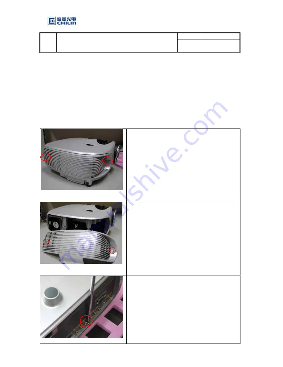
1. Loosen 2 screws from the Lamp Door.
2. Electric screw driver torque set for 11 lbs.
3. Take off the lamp door from the projector.
4. Electric screw driver torque set for 11 lbs.
5. Turn over the projector and loosen the screw by
the I/O port.
6. Electric screw driver torque set for 11 lbs.


