background image


optris CTratio 

– E2013-04-A 

23 


Programming Interface 


CTratio sensors can be optionally equipped with an USB-interface for 
programming of the sensor. 
If you want to install the interface, plug the interface board into the place 
provided, which is located beside the display. In the correct position the 
holes of the interface match with the thread holes of the electronic box. 
Now press the board down to connect it and use both M3x5 screws for 
fixing it. Plug the preassembled interface cable with the terminal block into 
the male connector of the interface board. 


If the USB interface is used the sensor is powered by the computer. If you use the laser and/ or display backlight we 
recommend an additional power supply. 
 
The usage of the USB interface is only recommended for programming purposes of the sensor. 
A continuous operation with interface is not permitted! 
 
Please pay attention to the notes in the according interface manuals. 

Summary of Contents for CTratio

Page 1: ...optris CTratio Fiber Optics Ratio Thermometer Operators manual ...

Page 2: ......

Page 3: ...at once The warranty period covers 24 months starting on the delivery date After the warranty is expired the manufacturer guarantees additional 6 months warranty for all repaired or substituted product components Warranty does not apply to damages which result from misuse or neglect The warranty also expires if you open the product The manufacturer is not liable for consequential damage or in case...

Page 4: ...fications 8 Definition 38 Measurement Specifications 9 Determination of unknown Emissivities 38 Optics 10 Characteristic Emissivities 39 Mechanical Installation 13 Characteristic Slope Values 40 Accessories 15 Determination of unknown Slope values 40 Laser Sighting 17 Attenuation 40 Electrical Installation 18 Appendix A Emissivity Table Metals 42 Cable Connections 18 Appendix B Emissivity Table No...

Page 5: ...ode 1C The 1 color mode is best for measuring the temperature of objects in areas where no sighting obstructions solid gases or dust exist The measurement object must fill completely the measurement spot if the 1 color mode is used 2 color mode 2C In this mode the object temperature will be determined from the ratio of the signal of two separate and overlapping infrared bands The 2 color mode is b...

Page 6: ...unting bracket adjustable in one axis Operators manual Maintenance Lens cleaning Blow off loose particles using clean compressed air The lens surface can be cleaned with a soft humid tissue moistened with water or a water based glass cleaner The CTratio sensing head is a sensitive optical system Please use only the thread for mechanical installation Avoid mechanical violence on the head this may d...

Page 7: ...nd USB interface The laser power at properly usage of the sensor fiber optical cable incl sensing head connected is 1mW and fulfils laser class 2 according IEC 60825 1 2007 Cautions Avoid static electricity The fiber optical cable has a minimum bending radius of 40 mm In case of problems or questions which may arise when you use the CTratio please contact our service department Read the manual car...

Page 8: ... at time of delivery Signal output object temperature 0 5 V Emissivity 1 000 Slope 1 000 Averaging AVG inactive Smart Averaging inactive Peak hold inactive Valley hold inactive Output channel 1 T 2C 2C temperature Lower limit temperature range C 700 Upper limit temperature range C 1800 Lower limit signal output 0 V Upper limit signal output 5 V Max attenuation 95 Temperature unit C Baud rate kBaud...

Page 9: ...ty 10 95 non condensing 10 95 non condensing Material stainless steel die casting zinc Dimensions length 78 1 mm SF head 89 mm x 70 mm x 30 mm 82 6 mm CF head thread M18x1 Weight 375 g incl fiber optics 3 m 420 g Fiber optics multimode fiber stainless steel armour Fiber optics length 3 m standard 6 m 10 m 15 m 22 m Vibration IEC 68 2 6 3G 11 200Hz any axis Shock IEC 68 2 27 50G 11ms any axis Softw...

Page 10: ... mA 0 5 10 V Digital I O pins 2 programmable in outputs usable as Alarm output open collector output 24 V 1 A Digital input for triggered signal output and peak hold function Output impedances mA max loop resistance 500 Ω at 8 36 VDC mV min 100 KΩ load impedance Digital interface USB optional for programming only Relay outputs 2 x 60 VDC 42 VACRMS 0 4 A optically isolated optional plug in module ...

Page 11: ... 0 1 K Response time 95 signal 5 ms 10 s 3 Emissivity 0 050 1 000 adjustable via programming keys or analog input Slope 0 800 1 200 adjustable via programming keys or analog input Signal processing One color Two color mode Attenuation monitoring Alarm Average Peak hold Valley hold Advanced peak hold with threshold and hysteresis adjustable via programming keys or software 1 at ambient temperature ...

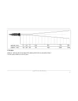
Page 12: ...40 1 CF2 optics 7 7 mm 305 mm D S 40 1 The following optical charts show the diameter of the measuring spot in dependence on the distance between measuring object and sensing head The spot size refers to 95 of the radiation energy The distance is always measured from the front edge of the sensing head SF optics ...

Page 13: ...optris CTratio E2013 04 A 11 CF2 optics distance distance from front edge of the sensing head to the measurement object The D S ratio is valid for the focus point ...

Page 14: ...ot should at all times have at least the same size like the object or should be smaller than that Sensor placement 2C mode In the 2 color mode the sensing head can be placed under various conditions like Measurement through holes smaller than the spot size Measurement through dust smoke or steam in the atmosphere Measurement of objects smaller than the measurement spot Measurement through a dirty ...

Page 15: ... sensor thread or with help of the hex nuts 2 pieces included in scope of supply to the mounting bracket available Various mounting brackets which make the adjustment of the sensing head easier can be additionally ordered as accessories Sensing head Please make sure that the minimum bending radius of the fiber optics of 40 mm will be considered during installation ...

Page 16: ...optris CTratio E2013 04 A 14 Electronic box The electronic box is also available with closed cover display and programming keys with no access from outside ACCTCOV ...

Page 17: ... clean at all times from dust smoke fumes and other contaminants in order to avoid reading errors in the 1 color mode These effects can be reduced by using an air purge collar Make sure to use oil free technically clean air only The needed amount of air approx 2 10 l min depends on the application and the installation conditions on site ...

Page 18: ...optris CTratio E2013 04 A 16 Rail Mount Adapter for Electronic box With the rail mount adapter the CTratio electronics can be mounted easily on a DIN rail TS35 according EN50022 ACCTRAIL ...

Page 19: ...automatically WARNING Inside the electronic box a HIGH POWER LASER is located The laser light is coupled into the fiber optics On the outlet at the optical head the laser power is 1mW and fulfils laser class 2 according IEC 60825 1 2007 Before you open the box remove the fiber optical cable from the electronics or disassemble the optical head the sensor must be switched off and disconnected from t...

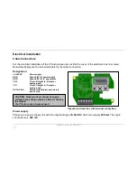
Page 20: ...ply GND Ground 0V of in and outputs I O 2 I O pin 2 digital In Output or analog input I O 1 I O pin 1 digital In Output or analog input OUT mV mA Analog output object temperature mV or mA Opened electronic box with terminal connections Power supply Please use a power supply unit with an output voltage of 8 36 VDC which can supply 200 mA The ripple should be max 200 mV CAUTION Please do never conne...

Page 21: ...xtract about 4 mm of the wire isolation and tin the wire ends Place the pressing screw the rubber washer and the metal washers of the cable gland one after the other onto the prepared cable end Spread the strands and fix the shield between two of the metal washers Insert the cable into the cable gland until the limit stop Screw the cap tight Every single wire may be connected to the according scre...

Page 22: ... find a black wire which is connecting factory default the ground connections GND power supply outputs with the ground of the electronics housing To avoid ground loops and related signal interferences in industrial environments it might be necessary to interrupt this connection ...

Page 23: ...can be done via the programming keys Operating The following output signals can be selected 0 5 V 0 10 V 0 20 mA 4 20 mA The following signal sources can be selected for output channel 1 T 2C 2C temperature T 1C 1C temperature Attenuation Signal attenuation in CAUTION Please do never connect a supply voltage to the analog outputs as this will destroy the output The CTratio is not a 2 wire sensor ...

Page 24: ...on of the Low level the last value will be held Valid HI input digital The output follows the object temperature as long as there is a High level at the I O pin After discontinuation of the High level the last value will be held Hold input digital The last value will be held if there is a signal with a rising edge on the I O pin Hold input digital The last value will be held if there is a signal w...

Page 25: ...onic box Now press the board down to connect it and use both M3x5 screws for fixing it Plug the preassembled interface cable with the terminal block into the male connector of the interface board If the USB interface is used the sensor is powered by the computer If you use the laser and or display backlight we recommend an additional power supply The usage of the USB interface is only recommended ...

Page 26: ... of the programming interface and the relay outputs is not possible The relay board provides two fully isolated switches which have the capability to switch max 60 VDC 42 VACRMS 0 4 A DC AC A red LED shows the closed switch The switching thresholds are in accordance with the values for the visual alarms LCD backlight To set the alarm values the digital programming interface USB and the software is...

Page 27: ...the I O pins can be programmed as alarm output In this case the pin acts as an open collector output 24 V 1A The following signal sources can be selected T 2C T 1C Attenuation TBox TProcess Temperature signal which has been selected for the analog output Different wirings of the open collector output For a setup of the alarm values selection of the signal sources and definition as high or low alar...

Page 28: ...ng routine for some seconds During this time the display will show INIT After this procedure the object temperature is shown in the display The display backlight color changes according to the alarm settings Alarms Visual Alarms Sensor Setup The programming keys Mode Up and Down enable the user to set the sensor on site The current measuring value or the chosen feature is displayed With Mode the o...

Page 29: ...temperature 1C 1C temperature AT attenuation A 0 2 Signal output Average 0 2 s A inactive 0 1 999 9 s P Signal output Peak hold inactive P inactive 0 1 999 9 s P oo oo oo oo infinite V Signal output Valley hold inactive V inactive 0 1 999 9 s V oo oo oo oo infinite u 700 0 Lower limit temperature range 700 C depending on model n 1500 Upper limit temperature range 1500 C depending on model 0 00 Low...

Page 30: ...pe Values E 0 970 Setup of Emissivity The emissivity is a material constant factor to describe the ability of the body to emit infrared energy The emissivity only affects measurements in the 1 color mode Emissivity D 95 0 Setup of the allowed Attenuation The temperature measurement will stop if the attenuation exceeds this limit Attenuation MD 2C Setup of the Main display on the electronic box By ...

Page 31: ...als The definition of the algorithm is according to the peak hold algorithm inverted u 700 0 Setup of the Lower limit of temperature range The minimum difference between lower and upper limit is 20 K If you set the lower limit to a value upper limit the upper limit will be adjusted to lower limit 20 K automatically n 1800 Setup of the Upper limit of the temperature range The minimum difference bet...

Page 32: ...optris CTratio E2013 04 A 30 Signal graph with P TProcess with Peak Hold Hold time 1s TActual without post processing ...

Page 33: ...emperature unit C or F M 01 Setup of the Multidrop address In a RS485 network each sensor will need a specific address This menu item will only be shown if a RS485 interface board is plugged in B 115k Setup of the Baud rate for digital data transfer ...

Page 34: ... start automatically Otherwise please start CDsetup exe from the CD ROM Follow the instructions of the wizard until the installation is finished The installation wizard will place a launch icon on the desktop and in the start menu Start Programs CompactConnect If you want to uninstall the software from your system please use the uninstall icon in the start menu Main Features Complete sensor setup ...

Page 35: ... Communication Settings Serial Interface Baud rate 9 6 115 2 kBaud adjustable on the unit or via software Data bits 8 Parity none Stop bits 1 Flow control off Protocol All sensors of the CTratio series are using a binary protocol ...

Page 36: ...e surface temperature on the basis of the emitted infrared radiation from an object The most important feature of infrared thermometers is that they enable the user to measure objects contactless Consequently these products help to measure the temperature of inaccessible or moving objects without difficulties Infrared thermometers basically consist of the following components lens spectral filter ...

Page 37: ... measured spot spatial peak picking instead of an average temperature A 2 color sensor can be mounted farther away even if the target does not fill the resulting spot size The convenience is that you are not forced to install the sensor at some specific distance based upon target size and the sensor s optical resolution Partially Obscured Targets The radiated energy from a target is in most cases ...

Page 38: ...h lower than the target temperature Example Measuring of wire or rod often too narrow for field of view or moving or vibrating unpredictably It is much easier to obtain accurate results because sighting is less critical with 2 color sensors Low or Changing Emissivities If the emissivities in both wavelengths colors were the same as they would be for any blackbody emissivity 1 0 or greybody emissiv...

Page 39: ...s the emissivity changes by the same factor in both wavelength bands Note however that accurate measurement results are dependent on the application and the type of material being measured To determine how to use 2 color sensors with your application when uncertain or changing emissivities are a factor please contact your sales representative ...

Page 40: ...suring results by interfering infrared radiation emitted by background objects flames heating systems chamottes To minimize measuring errors in such cases the handling should be performed very carefully and the unit should be protected against reflecting radiation sources Determination of unknown Emissivities First determine the actual temperature of the measuring object with a thermocouple or con...

Page 41: ...re of the colored surface CAUTION On all three methods the object temperature must be different from ambient temperature Characteristic Emissivities In case none of the methods mentioned above help to determine the emissivity you may use the emissivity tables Appendix A and B These are average values only The actual emissivity of a material depends on the following factors temperature measuring an...

Page 42: ...n Wolfram Determination of unknown Slope values Basically you can use the same methods to determine an unknown slope as described under Determination of unknown Emissivities As the CTratio is dedicated for high temperature applications only the first method may be practically applicable use of a t c or other contact probe Attenuation The CTratio is able to measure the temperature of targets smalle...

Page 43: ...ination of the optical transmission path in between the target and the ratio thermometer Due to the ratio principle the 2 channel signal upper curve stays very stable over a wide range of attenuation up to over 90 The signal of the 1 channel mode lower curve acting like in a standard pyrometer with one measuring wavelength only is decreasing rapidly with the contamination of the transmission path ...

Page 44: ...05 0 2 0 05 0 2 0 05 0 15 0 05 0 1 oxidized 0 2 0 8 0 2 0 9 0 5 0 8 0 4 0 8 Chrome 0 4 0 4 0 03 0 3 0 02 0 2 Gold 0 3 0 01 0 1 0 01 0 1 0 01 0 1 Haynes alloy 0 5 0 9 0 6 0 9 0 3 0 8 0 3 0 8 Inconel electro polished 0 2 0 5 0 25 0 15 0 15 sandblast 0 3 0 4 0 3 0 6 0 3 0 6 0 3 0 6 oxidized 0 4 0 9 0 6 0 9 0 6 0 9 0 7 0 95 Iron non oxidized 0 35 0 1 0 3 0 05 0 25 0 05 0 2 rusted 0 6 0 9 0 5 0 8 0 5 0...

Page 45: ... 0 2 0 4 0 1 0 3 0 1 0 15 0 05 0 15 oxidized 0 8 0 9 0 4 0 7 0 3 0 6 0 2 0 5 Platinum black 0 95 0 9 0 9 Silver 0 04 0 02 0 02 0 02 Steel polished plate 0 35 0 25 0 1 0 1 rustless 0 35 0 2 0 9 0 15 0 8 0 1 0 8 heavy plate 0 5 0 7 0 4 0 6 cold rolled 0 8 0 9 0 8 0 9 0 8 0 9 0 7 0 9 oxidized 0 8 0 9 0 8 0 9 0 7 0 9 0 7 0 9 Tin non oxidized 0 25 0 1 0 3 0 05 0 05 Titanium polished 0 5 0 75 0 3 0 5 0 ...

Page 46: ...m 0 95 0 9 0 9 Ceramic 0 4 0 8 0 95 0 8 0 95 0 95 Concrete 0 65 0 9 0 9 0 95 Glass plate 0 2 0 98 0 85 melt 0 4 0 9 0 9 Grit 0 95 0 95 Gypsum 0 4 0 97 0 8 0 95 Ice 0 98 Limestone 0 4 0 98 0 98 Paint non alkaline 0 9 0 95 Paper any color 0 95 0 95 Plastic 50 µm non transparent 0 95 0 95 Rubber 0 9 0 95 Sand 0 9 0 9 Snow 0 9 Soil 0 9 0 98 Textiles 0 95 0 95 Water 0 93 Wood natural 0 9 0 95 0 9 0 95 ...

Page 47: ...ntage of the average function is that fast temperature peaks which are caused by dynamic events are subjected to the same averaging time Therefore those peaks can only be seen with a delay on the signal output The function Smart Averaging eliminates this disadvantage by passing those fast events without averaging directly through to the signal output Signal graph with Smart Averaging function Sign...

Reviews: