background image

-


3.2


Installation (with visible camera) [hier Variante B] ......................................................................... 14


3.3


Mounting of the USB server ........................................................................................................... 14


3.4


Mounting of the PI camera ............................................................................................................. 16


3.5


Mounting of the Xi camera ............................................................................................................. 20


3.6


Mounting of CSlaser/CTlaser ......................................................................................................... 21


4


Accessoires ............................................................................................................................................ 23


4.1


Industrial Process Interface (PIF) ................................................................................................... 23


4.2


Wall mount ..................................................................................................................................... 24


5


Replacement of protective foil / protective window ........................................................................... 25


5.1


Disassembling air purge laminar .................................................................................................... 25


5.2


Removing and inserting the protective foil ..................................................................................... 27


5.3


Cut the protective foil ...................................................................................................................... 29


5.4


Assembly protective window .......................................................................................................... 31


Appendix A - Declaration of Conformity ...................................................................................................... 32


Summary of Contents for Outdoor protective housing

Page 1: ...Operator s Manual optris Outdoor protective housing for PI Xi camera CSlaser LT CTlaser LT USB server and industrial PIF ...

Page 2: ...Optris GmbH Ferdinand Buisson Str 14 13127 Berlin Germany Tel 49 30 500 197 0 Fax 49 30 500 197 10 E mail info optris global Internet www optris global ...

Page 3: ...1 1 Description 5 1 2 Warranty 6 1 3 Scope of Supply 6 2 Technical Data 7 2 1 General Specifications 7 2 2 Dimensions 8 2 3 Electrical Connections 10 2 4 Air Purge Laminar 11 2 5 Protective window 11 3 Installation 12 3 1 Electrical installation w o visible camera hier Variante A 12 ...

Page 4: ...0 3 6 Mounting of CSlaser CTlaser 21 4 Accessoires 23 4 1 Industrial Process Interface PIF 23 4 2 Wall mount 24 5 Replacement of protective foil protective window 25 5 1 Disassembling air purge laminar 25 5 2 Removing and inserting the protective foil 27 5 3 Cut the protective foil 29 5 4 Assembly protective window 31 Appendix A Declaration of Conformity 32 ...

Page 5: ...r any PI camera lenses up to 90 FOV and for CSlaser LT and CTlaser LT The integrated heating and the blower result in an extended operating temperature An optional visual camera is also available and can be also integrated to your process Avoid abrupt changes of the ambient temperature Avoid mechanical violence this may destroy the system expiry of warranty If you have any problems or questions pl...

Page 6: ...equential damage or in case of a non intended use of the product If a failure occurs during the warranty period the product will be replaced calibrated or repaired without further charges The freight costs will be paid by the sender The manufacturer reserves the right to exchange components of the product instead of repairing it If the failure results from misuse or neglect the user has to pay for...

Page 7: ... window 2 Germanium Ge zinc sulfide ZnS Borofloat or foil Environmental rating IP66 Air purge laminar Integrated Air pressure Absolute pressure 1 1 8 bar at 20 100 l min Max FOV 90 HFOV Integrated additional components USB Server Gigabit Industrial Process interface PIF Material Aluminum Weight 2 kg with wall mount 2 5 kg 1 The fan is switched parallel to the heater When the heater starts the fan ...

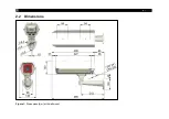
Page 8: ... 8 2 2 Dimensions Figure 1 Dimensions mm with wall mount ...

Page 9: ...Technical Data 9 Figure 2 Dimensions for wall mount ...

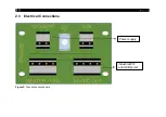
Page 10: ... 10 2 3 Electrical Connections Figure 3 Connection circuit board Power supply Industrial PIF and USB server ...

Page 11: ...Transmission 1 Germanium Protective window 50 8 x 3 mm Ge for PI 450i G7 640i G7 7 9 µm 0 96 Protective window 50 8 x 3 mm Ge for PI 400i 450i 640i 8 14 µm 0 92 Zinc sulfide Protective window 50 8 x 3 mm ZnS for PI 450i G7 640i G7 7 9 µm 0 93 Protective window 50 8 x 3 mm ZnS for PI 400i 450i 640i 8 14 µm 0 91 Protective window 50 8 x 3 mm ZnS for LT models of CTlaser CSlaser serie 8 14 µm 0 91 Bo...

Page 12: ...n the outdoor protective housing as shown in Figure 4 Figure 4 Opening the housing Inside the protective housing is the electronic circuit board where all loads are connected see Figure 3 The heating element and the fan are already integrated and connected To supply the outdoor protective housing ...

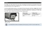
Page 13: ... side is a cable gland with 8 mm sealing insert and on the right is a cable gland with two 6 mm sealing inserts It is recommended to pull the Ethernet cable or the USB cable through the 8 mm sealing insert The PIF cable and the 24 V cable are passed through the two 6 mm sealing inserts Figure 5 Cable glands on the backside of the outdoor protective housing Cable gland 1 Cable gland 2 1 x 8 mm seal...

Page 14: ...t the USB server at a slanted angle to the designated disk Figure 6 If necessary remove the clip from the USB server Figure 7 and turn the USB server Figure 6 until the clip is locked into the bracket Figure 8 Figure 6 Insertion of the USB server into the provided board Figure 7 USB server clip Figure 8 USB server holding plate ...

Page 15: ...Installation 15 The USB server is now ready mounted Figure 9 Figure 9 USB server ready mounted ...

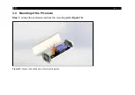
Page 16: ... 16 3 4 Mounting of the PI camera Step 1 Loosen the knurled screw from the mounting plate Figure 10 Figure 10 Loosen the knurled screw from mounting plate ...

Page 17: ...Installation 17 Step 2 Carefully remove the mounting plate Figure 11 Figure 11 Remove the mounting plate ...

Page 18: ...ment Mount the PI 400i 450i 640i 1M 08M 05M to the mounting plate using the supplied 1 4 x 3 8 UNC inch screw and a washer DIN125A 6 4 A2 Figure 12 After the camera is fully assembled the mounting plate can be attached back to the outdoor protective housing with the provided screw ...

Page 19: ...Installation 19 Figure 13 Fully assembled PI camera on mounting plate Figure 14 Fully assembled PI camera in outdoor protective housing ...

Page 20: ...rom the Xi camera Now screw the camera into the provided adapter plate For an exact positioning of the camera the camera can also be attached by turning the clamping ring Figure 15 Xi camera mounted in adapter plate Figure 16 Fully assembled Xi camera in outdoor protective housing ...

Page 21: ... corresponding bracket Mount the CSlaser or CTlaser to the mounting plate using the supplied 1 4 x 3 8 UNC inch screw and a washer DIN125A 6 4 A2 Figure 17 Note that the connector is facing outward to allow you to connect the cable The electronics box of the CTlaser must be installed outside the protective housing Figure 17 CSlaser CTlaser attachment ...

Page 22: ... 22 Figure 18 Mounted CSlaser or CTlaser on the mounting plate Figure 19 CSlaser or CTlaser in outdoor protective housing ...

Page 23: ... this case you can use the infrared camera and the visual camera just with one network cable the system can be powered over ethernet Both images can be integrated easily to your video surveillance software e g iSpy or other 4 2 Industrial Process Interface PIF In addition to the installation of the camera and the USB server the industrial PIF without housing can be integrated into the outdoor prot...

Page 24: ...ng of the PI camera or 3 5 Mounting of the Xi camera 4 3 Wall mount The outdoor protective housing can be attached to a wall using a wall mount This is available as an option under the part number ACOPHWM Figure 21 Outdoor protective housing with wall mount The wall bracket is mandatory for a mounting of the protective housing ...

Page 25: ...ed only for Part Number ACPIOPHF To change the protective foil a screwdriver and a scalpel is needed 5 1 Disassembling air purge laminar Step 1 Unscrew the 9 screws from the adapter plate using a screwdriver and remove them together with the washers Figure 22 Unscrew the screws Figure 23 Loosen 9 screws from the adapter plate Step 2 Gently remove the air purge laminar with O ring 1 ...

Page 26: ... 26 Figure 24 Remove air purge laminar ...

Page 27: ...rotective foil protective window 27 5 2 Removing and inserting the protective foil Step 1 Remove the old protective foil by removing the tension ring attachment and the tension ring Figure 25 Remove old protective foil ...

Page 28: ... O ring 2 in the air purge laminar Step 4 Place the protective foil on the center of the air purge laminar and press it with the aid of the tension ring and the tension ring attachment until the tension ring attachment is level with the air purge laminar Figure 26 Insert new protective foil ...

Page 29: ...e foil protective window 29 5 3 Cut the protective foil Step 1 Take a scalpel and cut along the inside of the nut Figure 27 Cut the protective foil with the scalpel Figure 28 Cut the protective foil along the nut inner surface ...

Page 30: ...air purge laminar and repeat the steps in chapter 5 1 reverse Make sure that the air purge laminar is pressed against the adapter plate when you tighten the screws again Figure 29 Air purge laminar Figure 30 Insert O ring 1 in air purge laminar O ring 1 ...

Page 31: ...eplacement of protective foil protective window 31 5 4 Assembly protective window Figure 31 Assembly protective window O ring 50x1 5 Clamping ring O ring 47x1 5 protective window Clamping ring attachment ...

Page 32: ... 32 Appendix A Declaration of Conformity ...

Page 33: ......

Page 34: ...optris Outdoor protective housing MA E2022 10 A ...

Reviews: