-
22
-
slight inclination of the camera is advantageous. More about this in chapter
The software PIX Connect uses the Linescan function to display a complete image although only one line is
scanned.
•
When installing the CT G5 sensor, make sure that it is positioned so that the optical beam path
runs between the individual rollers. Please refer to our
path.
•
During the glass measurement it must always be ensured that the glass runs over the sensor.
Otherwise, no referencing can take place and measurements can be incorrect.
•
The emissivity of the G5 sensor is preset to 0.92 (see chapter
).
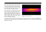
Now the control cabinet (
) must be moved to a
suitable position. The individual cable lengths are 10 m.
Therefore, make sure that the switch cabinet is no
further than 10 m from the camera or sensor.
Furthermore, make sure that it is not mounted in the
immediate vicinity of hot ambient temperatures.
Furthermore, it should be easily accessible, because
the trigger signal from the oven must be connected
here.
Figure 5:
Control cabinet
Summary of Contents for Top-down GIS
Page 1: ...Operators Manual Top down GIS Glass Inspection System ...
Page 5: ... Table of contents 5 Appendix A Control cabinet 43 ...
Page 11: ... Technical Data 11 Figure 1 Dimensions mm shutter system ...
Page 12: ... 12 Figure 2 Dimensions mm switch cabinet ...
Page 19: ... Technical Data 19 CT G5L SF optics ...
Page 34: ... 34 Figure 16 Linescan in PIX Connect software ...
Page 48: ...Top down GIS MA E2021 07 A ...


