-
Installation
23
-
Now that the three main components have been successfully assembled, two connections must be connected.
The first connection is the Ethernet cable to a computer or switch. The second connection is the power supply.
The entire system is supplied with 24 V. The power supply unit is included in the delivery.
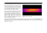
Another component of the system is the control unit. With this unit the shutters
can be opened and closed again. During the first installation it is necessary to
align the devices. This can only be done when the shutters are open.
When the system is powered, the yellow LED is on and the shutters are closed.
When the button is pressed, the shutters are opened and the LED goes off.
The green button is for measuring low-E glass. It is deactivated at first use.
Figure 6:
Control unit
Further notes and information on glass measurement can be found in chapter
Summary of Contents for Top-down GIS
Page 1: ...Operators Manual Top down GIS Glass Inspection System ...
Page 5: ... Table of contents 5 Appendix A Control cabinet 43 ...
Page 11: ... Technical Data 11 Figure 1 Dimensions mm shutter system ...
Page 12: ... 12 Figure 2 Dimensions mm switch cabinet ...
Page 19: ... Technical Data 19 CT G5L SF optics ...
Page 34: ... 34 Figure 16 Linescan in PIX Connect software ...
Page 48: ...Top down GIS MA E2021 07 A ...

