background image


Welcome Letter Rev 6 

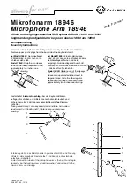
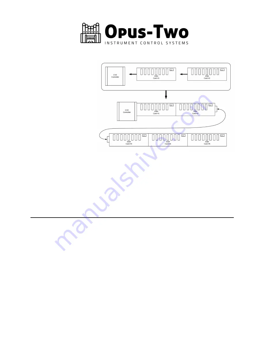
Laying Out The Card Chain 

The controllers and I/O 

cards get plugged together 

to make chains.  Refer to 

your documentation to 

know how long to make the 

console chain.  The console 

will get one controller and 

the appropriate number of 

I/O cards.  If the controller 

cards have come pre-

programmed, use the one 
marked “Console.”  The I/O 

cards are known by their 

relative position in the chain 

– the first card after the controller is card 1, next card is card 2, etc.   Any time you need to 

make a new row, simply use the Extender Card Kits with the cables provided.  The cables look 

like off-the-shelf Ethernet cables – they’re not.  Never substitute your own cables – if you need 

a different length, just let us know.  We will gladly send them to you.  Make sure you firmly seat 

the cable inside the connector, sometimes they click twice before being fully inserted. Please 

note that the drawing shows a legacy C-IV controller, but the concept applies the same with any 

controller. 


NEVER unplug a card from the chain while the power is on.  This will damage both cards. 


Summary of Contents for Instrument Control System

Page 1: ...t before even starting to build chamber panels this will provide all the knowledge you need to work in the chambers You will not have a programming cable per se with this control system The controller...

Page 2: ...controller is card 1 next card is card 2 etc Any time you need to make a new row simply use the Extender Card Kits with the cables provided The cables look like off the shelf Ethernet cables they re...

Page 3: ...slips this makes the control system extremely frustrating to use Separate additional pistons can be integrated into piston slips such as Mem Up Mem Dn Track Up Track Dn Transpose Transpose or any com...

Page 4: ...ypasses the internal fuse past fuse and allows larger amounts of current to surge quickly without risking an intermittent polyfused trip In other words connecting positive voltage to the VP terminal u...

Page 5: ...cards red or black PCB These cards have internal fusing and the power connector simply has two positive terminals and two negative terminals We suggest connecting an AWG14 wire to each terminal and ta...

Page 6: ...tch mode power supplies don t come up or go down very nicely at power up and power off and it is possible that odd behavior can occur stops moving for no reason etc This is not specific to Opus Two an...

Page 7: ...y are connected or not This means controllers can be freely unplugged from the PipeBus line and plugged back in as needed Many people use cat 5 cat 6 cable or even microphone cable for this The wire p...

Page 8: ...t which button puts the up down into transposer mode That wire should be connected to the transpose button 3 Once the transpose button is squared away hold down track and press up The track should inc...

Reviews: