background image


Welcome Letter Rev 6 

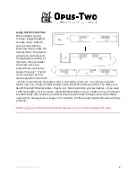
Locate and Install The Display


The display will get its “control buttons” mounted 

around it.  These are typically engraved pistons 

with no lamps.  If Walker pistons are used and 

they are being plugged into the display board, 

negative output is required for these particular 

pistons. 


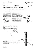
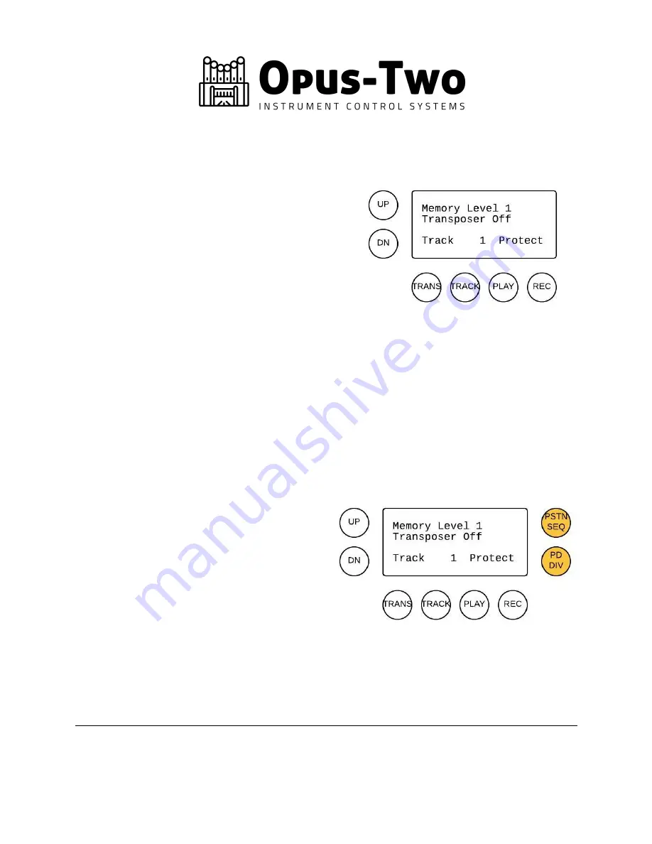
The pistons shown on the drawing at right are 

connected to the back of the display.  No other 

pistons are connected there.  See the CVE/CVA 
wiring diagram for more information in your wiring guide. 


Generally, the pistons should be arranged as shown in the drawing.  This allows the easiest 

interface and takes into account various buttons that must be pressed together.  As tempting as 

it may be to integrate the various buttons in piston slips, this makes the control system 

extremely frustrating to use.  Separate (additional) pistons can be integrated into piston slips, 

such as “Mem Up” , “Mem Dn” , “Track Up” , “Track Dn” , “Tra” , “Transpose -” , or any 

combination of the above.  Piston sequence buttons (previous and next) are also typically in the 

piston slips and not with the display. 


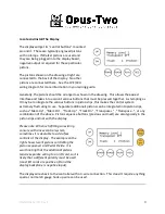
Please note: When retrofitting an existing 

console with a new control system, 

sometimes it is desirable to add a few 

controls at the display.  The example on the 

right shows two lit pistons controlling the 

piston sequencer and Pedal Divide.  It is 

worth noting that the additional pistons 

require separate wiring to an I/O card, so it is 

likely that a different polarity must be used 

(most I/O cards are positive I/O and the 

display backplane is negative input). 


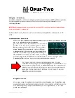
The display wires back to the controller with a 3-wire connection.  This doesn’t require anything 

special, normal 24 gauge hook up wire can be used. 


Summary of Contents for Instrument Control System

Page 1: ...t before even starting to build chamber panels this will provide all the knowledge you need to work in the chambers You will not have a programming cable per se with this control system The controller...

Page 2: ...controller is card 1 next card is card 2 etc Any time you need to make a new row simply use the Extender Card Kits with the cables provided The cables look like off the shelf Ethernet cables they re...

Page 3: ...slips this makes the control system extremely frustrating to use Separate additional pistons can be integrated into piston slips such as Mem Up Mem Dn Track Up Track Dn Transpose Transpose or any com...

Page 4: ...ypasses the internal fuse past fuse and allows larger amounts of current to surge quickly without risking an intermittent polyfused trip In other words connecting positive voltage to the VP terminal u...

Page 5: ...cards red or black PCB These cards have internal fusing and the power connector simply has two positive terminals and two negative terminals We suggest connecting an AWG14 wire to each terminal and ta...

Page 6: ...tch mode power supplies don t come up or go down very nicely at power up and power off and it is possible that odd behavior can occur stops moving for no reason etc This is not specific to Opus Two an...

Page 7: ...y are connected or not This means controllers can be freely unplugged from the PipeBus line and plugged back in as needed Many people use cat 5 cat 6 cable or even microphone cable for this The wire p...

Page 8: ...t which button puts the up down into transposer mode That wire should be connected to the transpose button 3 Once the transpose button is squared away hold down track and press up The track should inc...

Reviews: