


Welcome Letter Rev 6
4
Wiring the I/O Card Chain
Each I/O card (and the controller card) gets wired to power and ground. These DC connections
connect the green power connectors on the card to the console power distribution (not
normally provided).
NEVER
attempt to power up a console until all I/O card power connections have
been completely connected.
On the controller card, there are only two connection points (polarity is silkscreened on the
card).
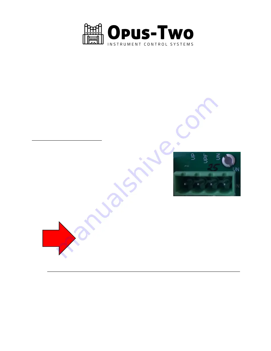
For IO64-LED cards (green PCB):
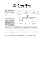
On the I/O cards, there are four power terminals: VP/VPF/VN/VN. The two VN terminals
are linked and therefore interchangeable
ground/common wires. The VP terminal is a fused feed
(in other words, the power goes through an on-board
fuse before being sent out the drivers; this is good for
almost every card in the console). The VPF terminal
bypasses the internal fuse (past fuse) and allows larger
amounts of current to surge quickly without risking an
intermittent polyfused trip. In other words, connecting
positive voltage to the VP terminal uses the internal fuse, and connecting it to VPF
bypasses the internal fuse. One or the other should be used, not both.
Tip: If a unit rank cuts in and out when being played with lots of
unification and coupling, it is probably tripping the internal polyfuse. Any
time an internal polyfuse trips, an LED illuminates in the upper left corner
of the card to indicate that it had tripped. The LED remains illuminated
even after the fuse resets itself. Be aware the polyfuse self-reset can
take a few seconds to complete.
Fusing Requirements
We suggest fusing the positive side of each I/O card with a glass fuse. These fuses exist
only protect against an otherwise catastrophic short circuit, such as a solder blob on the
card, reversed polarity, component meltdown, etc. The negative wires to the cards
should never be fused.