


Welcome Letter Rev 6
7
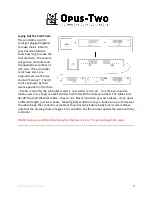
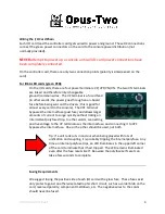
Connecting Console to Chambers
If your control system is so small that there is only one controller card, this section doesn’t
apply to you. Otherwise, on each chamber controller card is a green 3 pin connector.
Connecting the 3 pin connector in the chamber to one of the 3 pin connectors in the console
per the wiring diagrams. This will provide all that is needed for communication between he
two locations. This green connection and wiring is known as the PipeBus connection. Pins A
and B carry data; Pin C is the reference ground (Pin A is closest to the Analog In headers on a
CVA; Pin A is closest to the MIDI ports on a CVE). If a chamber card doesn’t have a functioning
console attached, it will have all pins held off (will not chirp or burp). Consoles transmit to
chambers whether they are connected or not. This means controllers can be freely unplugged
from the PipeBus line and plugged back in as needed.
Many people use cat 5/cat 6 cable or even microphone cable for this. The wire pattern can be
“hub and spoke” where each chamber wires back to the console and parallels at the console
connector, or “daisy chain” where the signal goes to one chamber, jumps to the next, etc. or
any combination of these methods. For reliability, we suggest to only using stranded cable to
connect the data links.
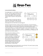
Powering Up the Console
Before powering up the console, make sure the uSD card is installed in the controller (unlike
past systems, there is no adapter – the card simply plugs into a socket on the controller).
When power is first applied, the display will have a startup message, which will be replaced
with another screen as the console boots. Within a few seconds, the console should be
completely up and running. The screen will say “Folder 1” or “Mem Level 1” on the top line if
the console is up and running.