


Welcome Letter Rev 6
8
Checking the Basics (in the console)
Each of these steps is provided in intentional sequence, do not jump ahead or else you could
skip something important that needs to be verified.
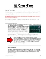
Remember that before even touching the “digital” side of the control system, you can use the
LEDs on the cards to verify individual items (such as key contacts, stop sense lines, etc.)
1)
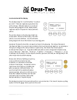
Does the display show “Memory Level” and/or “Track” on it? If not, verify that the
controller card has 12 volts and ground connected to it (use a volt meter). If it does and
you still have a blank screen (or any screen other than the correct one), turn off power
and diagnose the 3 wire connection between the C-IV controller card and the display.
2)
Once the display has the correct screen on it, press the “Up” and “Down” buttons and
verify that the memory level changes with the button presses. If it doesn’t, look closely
at the wiring between the buttons and the display. Make sure that the buttons are
connecting 0V (ground) to the pins on the back of the display. Once the up and down
buttons are functional, try one quick press on the transposer button, then use the up
and down buttons. Does the transposer then go up and down? If not, figure out which
button puts the up/down into transposer mode. That wire should be connected to the
transpose button.
3)
Once the transpose button is squared away, hold down track and press up. The track
should increase. If it doesn’t, then work your way around the buttons until you figure
out which button (when held) makes up/down change the track.
4)
Once the display is verified to be properly functioning, get to the home screen (if you
have somehow wandered to a different screen, just press the reset button on the
console controller). Using the USB Terminal (instructions further in this book), check
each card’s wiring.
5)
One stop at a time, turn on the stop and press cancel. If any stops don’t cancel, verify
that a coil is being energized by checking the LED and then figure out whether that
impulse is getting to the stop coil or not. It may be helpful to make a list, you may see
patterns that help identify problems.
6)
Once every single stop is cancelling correctly and every single piston is wired and
mapped correctly, follow the instructions in the organist manual for setting piston
ranges.
7)
Now test combination action. As tempting as it is, start very small and move up. Set a
few stops, test. Set a few more stops, test. Eventually you can alternate between
setting full registrations and general cancel.
8)
At this point, it is appropriate to build chamber panels, install them, wire them, and try
playing pipes from the console.