DA-4PM/0 version 1.0.E
6
Mainframe for
4 modular amplifiers
DA-4PM/0
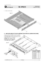
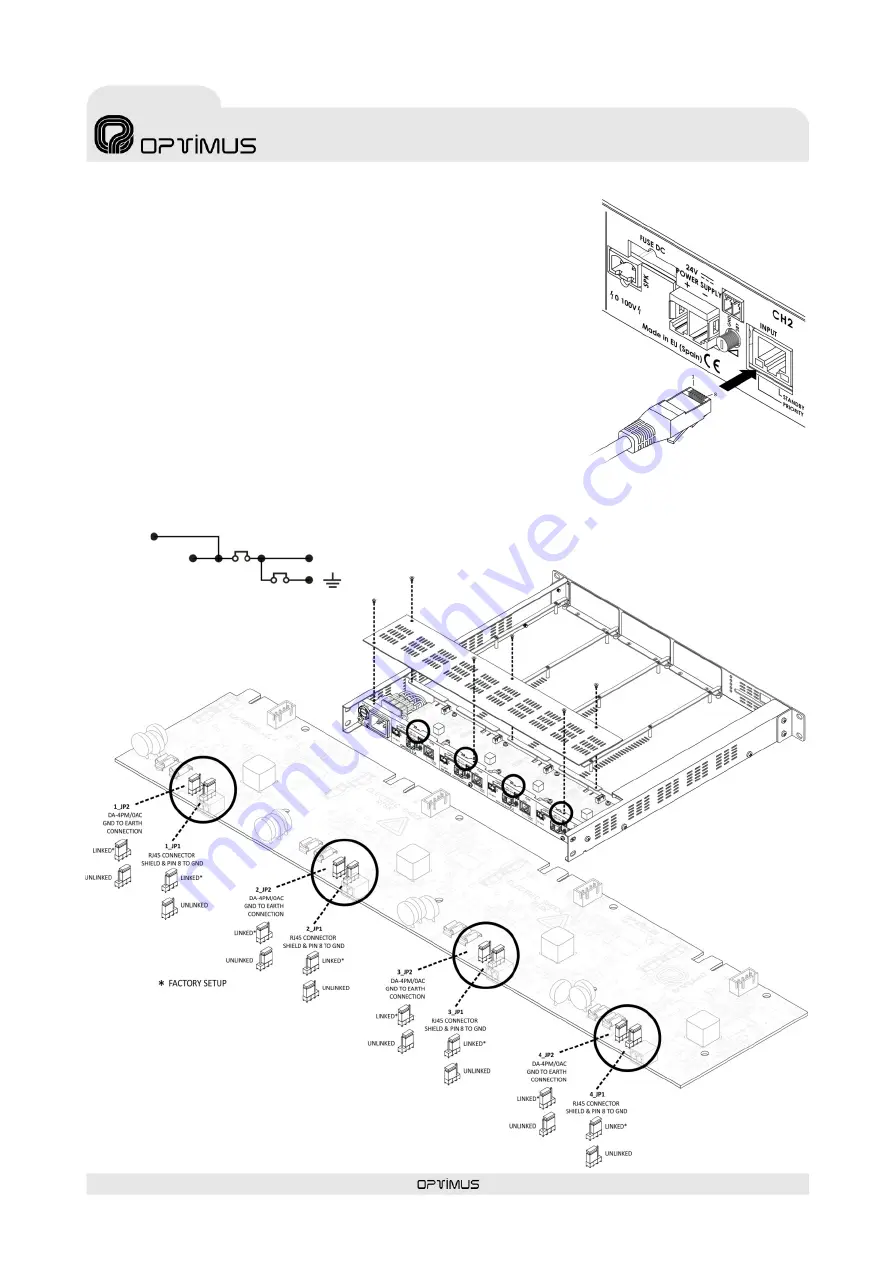
The connection between the pin 8 and the shielding of the RJ45 connector to the GND
of the DA-4PM/0, and the connection between the GND to the earth of the DA-4PM/0,
is made through the internal jumpers. By default, they are linked. If the installation
requires it, you can isolate by means of these internal jumpers. See figure 5.
4.2.
Inputs connection
RJ45 Connectors. Each of the inputs corresponds to an amplifier.
Unbalanced inputs. Sensitivity of 0dB (775 mV rms).
Pin 1:
AUDIO INPUT HOT.
Pin 2:
GND (or AUDIO INPUT COLD if audio signal input is balanced).
Pin 3:
Power supply output. MP-WD1 amplifier series voltage: +15VDC. MP-WDC
amplifier series voltage: +30VDC. Used for amplifier surveillance or to
provide a voltage which can be used to power low consumption devices.
The maximum current supplied is 140 mA.
Pin 4:
Not used.
Pin 5:
Not used.
Pin 6:
PRIORITY INPUT CONTACT. By connecting this contact to ground, the
amplifier is ON even though the STANDBY contact is activated. If the hot
swapping screw is not screwed, the amplifier would remain in standby
mode even if the priority contact is activated.
Pin 7:
Not used.
Pin 8:
Metal Shield:
Internal
jumpers
x_JP1
GND
Internal
jumpers
x_JP2
Figure 4
Figure 5
INPUT 4
INPUT 3
INPUT 2
INPUT 1


