background image

Chapter 2

Installing the External I/O Expansion Unit in a Rack

2-7

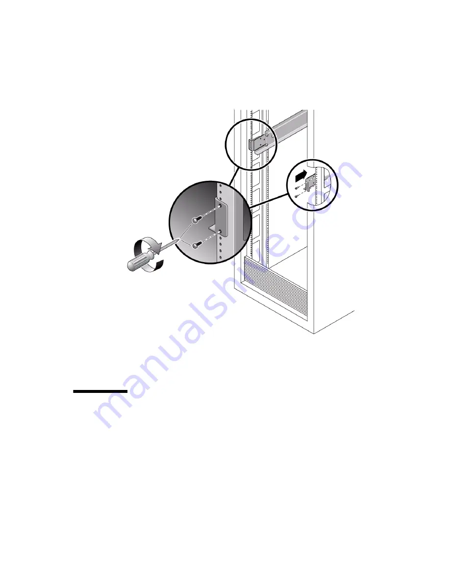
FIGURE 2-5

Installing the Mounting Brackets in a Rack

8. Tighten the screws at the front of the rack.

9. Verify that the brackets at the rear of the rack can still slide slightly to the left

and right.

2.3

Installing the External I/O Expansion
Unit in the Rack

The External I/O Expansion Unit can be installed in either an expansion rack or the
19-inch rack space in the SPARC Enterprise M8000 server.

1. Use an antistatic strap for this procedure.

Summary of Contents for SPARC Enterprise M4000

Page 1: ...External I O Expansion Unit for SPARC Enterprise M4000 M5000 M8000 M9000 Servers Installation and Service Manual Part No E22742 01 Manual Code C120 E329 07EN April 2011 ...

Page 2: ...tered trademarks of Fujitsu Limited All SPARC trademarks are used under license and are registered trademarks of SPARC International Inc in the U S and other countries Products bearing SPARC trademarks are based upon architectures developed by Oracle and or its affiliates SPARC64 is a trademark of SPARC International Inc used under license by Fujitsu Microelectronics Inc and Fujitsu Limited Other ...

Page 3: ...es déposées de Fujitsu Limited Toutes les marques SPARC sont utilisées sous licence et sont des marques déposées de SPARC International Inc aux États Unis et dans d autres pays Les produits portant la marque SPARC reposent sur des architectures développées par Oracle et ou ses sociétés affiliées SPARC64 est une marque de SPARC International Inc utilisée sous licence par Fujitsu Microelectronics In...

Page 4: ......

Page 5: ... 2 2 Fans 1 6 1 1 3 I O Boats 1 7 1 2 Card Slots 1 9 1 2 1 Carriers 1 9 1 2 1 1 Carrier Slots 1 10 1 2 1 2 Dummy Cards 1 11 1 2 2 Link Kits 1 12 1 2 3 Cable Management 1 13 1 2 3 1 Minimum Bend Radius for Link Cables 1 15 1 2 3 2 Cable Management Unit 1 16 1 3 Carriers 1 17 1 3 1 Carrier Removal and Insertion 1 18 1 3 2 Card Locks 1 20 ...

Page 6: ...27 1 3 5 1 Tilted Cards 1 27 1 3 5 2 Hidden Problems 1 29 1 3 6 Carrier Keys 1 33 1 4 External I O Expansion Unit Configurations 1 34 1 4 1 Single Boat Configuration 1 34 1 4 2 Dual Boat Configuration 1 35 1 5 LEDs 1 36 1 6 System Management 1 38 1 6 1 Maximum Temperatures in the External I O Expansion Unit 1 39 1 7 Site Preparation 1 39 1 7 1 Physical Requirements 1 39 1 7 2 Electrical Requiremen...

Page 7: ...efore Service 4 6 4 4 1 The cfgadm c disconnect Command 4 6 4 4 2 Example of the cfgadm c disconnect Command 4 6 4 5 Preparing the Cable Plate for Service 4 7 4 6 Replacing a Carrier 4 9 4 7 Replacing a Link Cable 4 13 4 8 Replacing a Link Card in the Host Server 4 13 4 9 Replacing a Link Card in an I O Boat 4 14 4 10 Installing a Second I O Boat 4 16 4 11 Replacing an I O Boat 4 19 4 11 1 Replaci...

Page 8: ...or Service Access A 2 A 3 Environmental Specifications A 3 A 4 Power Source Requirements A 4 A 5 Acoustic Noise Emissions A 4 A 6 Agency Compliance Specifications A 5 B External I O Expansion Unit LED Status Indicators B 1 B 1 LED Locations B 2 B 2 LED States B 4 C PCI Cards and Device Mapping C 1 C 1 Device Mapping C 1 C 2 Device Map Examples C 3 C 2 1 Device Map for PCI Express Cards C 3 C 2 2 D...

Page 9: ... When Accessing the Link Card Installed in the Host D 11 D 2 3 Management Bus Failures D 12 D 2 4 Cable Removed or Power Loss D 13 D 2 5 Interrupt Signal Failures D 14 D 2 6 FRU Discovery Failures D 15 D 2 6 1 Signal Failure D 15 D 2 6 2 Boat Not Monitored D 16 D 2 6 3 Link Card Mode Failure D 17 D 2 6 4 Boat Location Failure D 17 D 2 7 Reported Failures on the Microcontroller D 19 D 2 7 1 Fan Con...

Page 10: ...x External I O Expansion Unit for SPARC Enterprise Mx000 Servers Installation and Service Manual April 2011 ...

Page 11: ...tions External I O Expansion Unit Documents on page xi Text Conventions on page xii Notes on Safety on page xiii Documentation Feedback on page xiii External I O Expansion Unit Documents All documents for your External I O Expansion Unit are available online at the following locations Oracle documents http download oracle com docs cd E19322 01 index html Fujitsu documents http www fujitsu com spar...

Page 12: ...ide Fonts symbols Meaning Example AaBbCc123 What you type when contrasted with on screen computer output This font represents the example of command input in the frame XSCF adduser jsmith AaBbCc123 The names of commands files and directories on screen computer output This font represents the example of command input in the frame XSCF showuser P User Name jsmith Privileges useradm auditadm Italic I...

Page 13: ...iance Guide SPARC Enterprise M3000 M4000 M5000 M8000 M9000 Servers Important Legal and Safety Information Documentation Feedback If you have any comments or requests regarding this document go to the following web sites For Oracle users http www oraclesurveys com se ashx s 25113745587BE578 For Fujitsu users http www fujitsu com global contact computing sparce_index html ...

Page 14: ...xiv External I O Expansion Unit for SPARC Enterprise Mx000 Servers Installation and Service Manual April 2011 ...

Page 15: ...slots This chapter contains the following topics Section 1 1 General Description on page 1 2 Section 1 2 Card Slots on page 1 9 Section 1 3 Carriers on page 1 17 Section 1 4 External I O Expansion Unit Configurations on page 1 34 Section 1 5 LEDs on page 1 36 Section 1 6 System Management on page 1 38 Section 1 7 Site Preparation on page 1 39 Section 1 8 Service Information on page 1 41 Section 1 ...

Page 16: ...l I O Expansion Unit which are described separately in this chapter Note All slot numbers run from left to right regardless of whether you are viewing the front or the back of the External I O Expansion Unit At the front of the External I O Expansion Unit the power supplies are numbered from left to right I O boats at the rear of the External I O Expansion Unit are also numbered from left to right...

Page 17: ...Unit 1 7 Internal AC cable 3 Power Supply Unit 0 8 Cable management unit One of two types is included Type 8a routes cables to both sides of a rack Type 8b routes cables only the right side of a rack 4 Centerplane 9 Link kit One of two types is included 9a is the copper link kit 9b is the optical link kit 5 I O boat 0 3 2 5 6 7 1 9a 4 9b 8a 8b ...

Page 18: ...PSUs or I O boats Transfer the PSUs and I O boats from the damaged chassis to the replacement chassis Each internal AC cable supplies only one PSU To ensure redundant power use the two AC cords supplied with the External I O Expansion Unit to connect the internal AC cables to separate AC sources Caution Do not connect the internal AC cables directly to a power strip Use the the AC power cords supp...

Page 19: ...xpansion Unit has two power supply units PSUs for redundancy See FIGURE 1 3 Each PSU includes an integral fan FIGURE 1 3 Power Supply Unit Figure Legend 1 PSU 5 Fan 2 Handle locking screw 6 Caution labels 3 Handle 7 PSU slot 0 4 AC switch 8 PSU slot 1 1 2 3 4 5 7 8 6 ...

Page 20: ...U is the cable terminating nearest that PSU slot The PSUs should be connected to two independent external AC power sources so that service will not be interrupted if one AC power source fails 1 1 2 2 Fans A fan is located in the front of each PSU If one fan fails the remaining fan supplies enough air to cool two I O boats Note The fan might turn on when you insert a PSU into the External I O Expan...

Page 21: ...re not interchangeable between the two types of boats The PCI X I O boat accepts PCI X cards and some older types of PCI cards The PCI Express I O boat accepts PCI Express cards up to x8 lanes wide PCI Express x16 cards do not fit in this boat Figure Legend 1 I O boat 5 Boat slot 0 2 Captive screws 6 Boat slot 1 3 Link card carrier slot 0 7 Caution labels 4 PCI card carriers slots 1 6 1 3 4 5 6 2 ...

Page 22: ... the switches and bridges are displayed in the output of OpenBoot PROM probing However the link cards themselves never appear during OpenBoot PROM probing For examples of OpenBoot PROM output see Appendix C Note A bridge is a device that converts PCI Express and PCI X signal formats and connects multiple busses to a single bus A switch is a device that connects multiple busses to a single bus with...

Page 23: ...ts up to x8 card sockets PCI Express x16 cards are not supported in the PCI Express I O boat Note Graphics cards are not supported Caution Do not insert a x16 PCI Express card in an I O boat The x16 card connector is too large for the x8 card socket and will damage the socket 1 2 1 Carriers All PCI cards in the External I O Expansion Unit are mounted on carriers FIGURE 1 25 Carriers control RFI em...

Page 24: ...de dummy cards The dummy cards help the carriers to stay in place and to control the passage of air through the I O boat For information about dummy cards see Section 1 2 1 2 Dummy Cards on page 1 11 1 2 1 1 Carrier Slots There are seven carriers in each I O boat FIGURE 1 6 Carriers can be adjusted to fit various sizes and shapes of PCI cards Link cards use the same type of carrier Carrier slot 0 ...

Page 25: ...e that there are differences in their edge connectors FIGURE 1 7 Dummy Cards Note Be certain that the dummy cards are fully seated This action minimizes the vibration of unused carriers in the I O boat slots The service labels not shown in FIGURE 1 7 on the dummy cards include simplified instructions for removing and installing PCI cards Figure Legend 1 PCI Express version 2 PCI X version PCI E PC...

Page 26: ... boat 1 2 2 Link Kits One link kit is required for each I O boat A link kit includes two link cards One link card goes into the host server The other link card goes into the I O boat The link cards are physically identical Two link options are available a copper link kit and an optical link kit FIGURE 1 8 The copper link kit has one bidirectional cable A low profile bracket is included so a link c...

Page 27: ... rack There are two types of cable management units Some racks allow the routing of cables along both sides of the rack The type A cable plate FIGURE 1 9 supports cable routing along both the left and right sides of the rack Some racks allow routing of cables only along the right side of the rack The type B cable plate FIGURE 1 10 is optimized for cable routing along the right side of the rack ...

Page 28: ...Enterprise Mx000 Servers Installation and Service Manual April 2011 FIGURE 1 9 Cable Management Unit Type A for Routing Cables to Both Sides of the Rack Figure Legend 1 Type A cable plate 2 Support brackets 3 Cable plate locking screws 1 2 2 3 3 ...

Page 29: ...tion unit route the cable on the left side of the rack 1 2 3 1 Minimum Bend Radius for Link Cables The link cables might be damaged if they are coiled too tightly The minimum bend radius for the copper link cable is 1 85 in 47 mm The minimum bend radius for optical link cables is 1 8 in 46 mm Figure Legend 1 Type B cable plate 2 Support brackets 3 Cable plate locking screws 1 2 2 3 3 ...

Page 30: ...osition the cable plate rests on the support brackets In the raised position the cable plate rests slightly above the support brackets This position provides clearance for you to remove and replace an I O boat FIGURE 1 11 Cable Plate Side Views of Normal and Service Positions 1 3 Carriers In the I O boat all PCI cards are mounted on carriers When you insert the carrier and card into the boat and p...

Page 31: ...avoid premature failure of the carrier do not repeatedly open and close the carrier more than is necessary to familiarize yourself with its operation FIGURE 1 12 Carrier FIGURE 1 13 shows the details of a typical carrier Figure Legend 1 PCI card 2 Carrier 3 Carrier handle in unlocked position 1 2 3 ...

Page 32: ...0 mm A small metal latch item 3 in FIGURE 1 14 is located at the front of the carrier The latch locks the carrier handle in the extended position This action prevents the carrier plate and PCI card from falling and damaging the PCI slot connector as you pull the carrier unit out of the carrier slot Figure Legend 1 Carrier main body metal 4 Carrier handle 2 Carrier plate plastic 5 Card locks see Se...

Page 33: ...ore vertical clearance for a PCI card when you install or remove the PCI card When you insert the carrier into the I O boat the latch automatically unlocks itself FIGURE 1 14 Carriers Caution All carriers must contain either a PCI card or a dummy card to avoid loss of cooling air Figure Legend 1 Pull carrier handle to raise PCI card out of PCI slot socket 2 Push carrier handle and latch 3 to lower...

Page 34: ...n order for the carrier to correctly seat the PCI card in the card socket in the I O boat FIGURE 1 15 Card Locks There are three types of locks Type A is a square shaped lock Three of these are supplied with each carrier Type B is an oblong lock that has an S shaped profile It provides a longer extension 0 75 in 19 mm than type A Type B can be used as a top or side mount wherever a longer reach is...

Page 35: ...nation of card locks that is best suited to the size and shape of the PCI card 1 3 3 Tightening Sequence for Card Locks To fasten a PCI card to a carrier so that the card will seat reliably tighten the card locks in the sequence shown in FIGURE 1 16 or FIGURE 1 17 PCI card shapes and sizes can vary so use the following instructions as suggestions not as strict requirements If the PCI card is wide ...

Page 36: ...card lock number 1 in FIGURE 1 16 to ensure that the bottom of the PCI card is perfectly horizontal then tighten the remaining card locks in the sequence shown 1 3 3 2 Tightening Sequence for Narrow Cards FIGURE 1 17 Card Lock Sequence for Narrow Cards Tighten the upper left card lock number 1 in FIGURE 1 17 while ensuring that the card is perfectly horizontal Then tighten the remaining card locks...

Page 37: ...Use TABLE 1 1 to select locks that are best suited to your PCI card TABLE 1 1 Card and Lock Styles Suggested Lock Type PCI Card Shape Top Lock Card Height Side Lock Card Width Bottom Lock Example Wide Type A x2 Type A 12 in 304 mm maximum card width Type C FIGURE 1 18 Average width Type A x2 Type A 5 75 in 146 mm minimum card width Type B 5 0 in 127 mm minimum card width Type C FIGURE 1 18 Narrow ...

Page 38: ...card if the lock will be in a location that causes the lock to interfere with the PCI card connector in the I O boat Do not use the type C lock to support the bottom of a card if the lock will be in a location that causes the lock to interfere with the PCI card connector in the I O boat Do not use the type C lock to support the bottom of a card if the lock will be in a location that causes the loc...

Page 39: ...on top 1 type A on right 1 type C on bottom of the PCI card 2 Tall and average width card 2 type A on top 1 type A on right 1 type C on bottom of the PCI card 3 Tall and narrow card 1 type A on top 1 type A on right 1 type C on lower right side of the PCI card 4 Tall and very narrow card 1 type A on top 1 type B on right 1 type C on lower right side of the PCI card 1 2 3 4 ...

Page 40: ...s With Low and Very Low Height PCI Cards FIGURE 1 19 Lock Arrangements for Low and Very Low Height PCI cards Figure Legend 1 Low height card 2 type A on top 1 type A on right side 1 type C on lower right side of the PCI card 2 Very low height card 1 type B on top 1 type A on right edge 1 type C on lower right side of the PCI card 1 2 ...

Page 41: ...d can slip and tilt during seating when you do not apply enough pressure on a PCI carrier card lock when mounting the card on the carrier A less common problem is that the bracket of a PCI card will bend when you apply too much pressure on a PCI carrier card lock when mounting the card on a carrier Figure Legend 1 Very low height and narrow width card 1 type B on top 1 type C on right side of the ...

Page 42: ...o low to accept a lock the card cannot be used 2 Find a lock to fit the top of the card and provide side support to prevent the card from tilting A tilted card FIGURE 1 21 will not seat properly 3 Support of the bottom of the card is not a major priority because the carrier plate itself provides some support for the bottom of the card 4 Use only enough pressure to hold the lock against the PCI car...

Page 43: ...ment post FIGURE 1 22 and FIGURE 1 23 Card alignment tab FIGURE 1 22 Internal RFI gasket FIGURE 1 24 Alignment Post and Alignment Tab The card alignment post and the card alignment tab help to keep the front of the PCI card in the correct vertical orientation with support from properly installed card locks FIGURE 1 22 Card Alignment Post and Card Alignment Tab Figure Legend 1 Card alignment post 2...

Page 44: ...t with the socket in the I O boat The tab item 2 in FIGURE 1 22 fits in a notch at the bottom of the PCI card The tab helps to align the card when you install it in the carrier Note that some card types might not have the notch Note The tab lifts the front of the card out of the card connector when you remove the carrier from the I O boat If you cannot use a type C lock FIGURE 1 15 to support the ...

Page 45: ...Chapter 1 Overview 1 31 FIGURE 1 23 Card Alignment Post Detail Figure Legend 1 Carrier front housing 2 Card alignment post 3 PCI card bracket 1 2 3 ...

Page 46: ...at the bottom of the metal card bracket does not scrape or loosen the bottom of the gasket FIGURE 1 24 The gasket material is flexible enough that you might not notice that the bracket has dislodged the gasket Remember to inspect the condition of this gasket before you install the carrier in the I O boat FIGURE 1 24 Internal RFI Gasket Figure Legend 1 PCI card 2 RFI gasket extends to the bottom fr...

Page 47: ... Key If you replace a carrier install the key in the keyhole that corresponds to the slot that you use A replacement carrier includes one key It also includes an assortment of labels Affix the appropriate label LINK 0 PCIE n or PCIX n to the front of the replacement carrier for easy identification Figure Legend 1 Key M2 screw 2 Hole locations for carrier slots 0 1 2 3 front row Hole locations for ...

Page 48: ...er panel in the second boat bay FIGURE 1 26 shows a host server and a base External I O Expansion Unit in the same rack A link card in the host server connects to a link card in the External I O Expansion Unit One or two link cables connect the two link cards The cables are not shown to scale The copper link kit includes a single 13 ft 4 m link cable The optical link kit includes two link cables T...

Page 49: ...RX Sockets 1 4 2 Dual Boat Configuration The dual boat configuration provides twelve I O slots Each of the I O boats requires its own link kit so the host server must have two I O slots available for this purpose Figure Legend 1 External I O Expansion Unit 2 Host server 1 2 ...

Page 50: ...ver but not to a domain on a different server Note Do not daisy chain two boats connect a boat to another boat through link cards Daisy chain configurations are not allowed 1 5 LEDs LEDs are located on the front FIGURE 1 27 and rear FIGURE 1 28 of the chassis and on individual PSUs See Appendix B for information about interpreting LED states FIGURE 1 27 LEDs on the Front of the Chassis Figure Lege...

Page 51: ...an also manually turn on the LED by pressing the button FIGURE 1 28 LEDs on the Rear of the Chassis 4 Chassis overtemp 10 PSU1 fault locate 5 PSU0 ready to remove 11 PSU1 DC power 6 PSU0 fault locate 12 PSU1 AC power Figure Legend 1 Chassis locate LED and switch 8 I O boat 1 ready to remove 2 Chassis fault service required 9 I O boat 1 fault locate 3 Chassis power 10 I O boat 1 DC power 4 Chassis ...

Page 52: ...rature data and FRU ID information is available on an I2C bus Inter IC bus in the External I O Expansion Unit and the link cards The service processor in the host system can monitor the I2C bus in the External I O Expansion Unit The service processor can power down the External I O Expansion Unit if parameters exceed maximum limits There is no service processor in the External I O Expansion Unit i...

Page 53: ... External I O Expansion Unit with the cable management unit attached is 17 3 in 440 mm wide and 39 4 in 1000 mm deep The movement of air through the External I O Expansion Unit chassis is from front to back The External I O Expansion Unit is four rack units tall 6 9 in 175 mm TABLE 1 2 Maximum Temperatures Temperature Where Measured Comments 38 C 100 F At the intake of the PSU Ereport ereport chas...

Page 54: ...ly 81 pounds 36 8 kg Caution Mount the heaviest subassemblies at the lowest available opening in a rack to minimize the precarious effects of a top heavy system Note Do not install another product between two External I O Expansion Units if the product is short in height and shorter in depth than the External I O Expansion Units If there is little space between the upper and lower External I O Exp...

Page 55: ...rnal I O Expansion Unit is mounted on fixed brackets Sliding brackets are not available for this product PCI card installation To avoid overheating of the External I O Expansion Unit cards should be installed as quickly as possible To prepare yourself to install a card within one or two minutes see Section 1 3 Carriers on page 1 17 PCI cable removal When removing cables such as LAN cables if you h...

Page 56: ... upside down Jumpers The External I O Expansion Unit does not have jumper pins For information about any jumper pins that might be present on a specific PCI card see the instructions that came with the card System serial number For a new system the system serial number is located on labels on the chassis bezel and inside the right I O boat bay For a FRU chassis the system serial number is located ...

Page 57: ... produced by walking across a carpet and touching a board or by other similar cause Before handling any board ensure that you dissipate your body s charge Touch a conductive surface of the chassis or other element connected to common earth ground to discharge the static electricity present in your body To minimize risk of ESD damage Handle the board by the edges only Store the board in an antistat...

Page 58: ...1 44 External I O Expansion Unit for SPARC Enterprise Mx000 Servers Installation and Service Manual April 2011 ...

Page 59: ...ng the External I O Expansion Unit in the Rack on page 2 7 Section 2 4 Installing the Cable Management Unit on page 2 9 Section 2 5 Installing the AC Cords on page 2 13 Section 2 6 Installing the Link Kit on page 2 16 2 1 Tools You need the following tools for this installation Phillips No 1 screwdriver Phillips No 2 screwdriver ESD protected mat and a grounding strap Suggested digital voltmeter t...

Page 60: ...ternal I O Expansion Unit mounting kit FIGURE 2 1 includes a right side mounting bracket and a left side mounting bracket The mounting brackets are adjustable for length and are shipped unassembled The mounting kit includes two chassis lock brackets FIGURE 2 1 Mounting Kit 1 Use an antistatic strap for this procedure 2 Locate a suitable mounting location in the rack Figure Legend 1 Left mounting b...

Page 61: ...on Unit install them together Do not install a shorter subassembly between External I O Expansion Unit where the rear of the shorter subassembly might difficult to reach If the rack is marked with rack units place the mounting bracket so that the lower screw hole on the bracket is one hole above an RU mark FIGURE 2 2 This aligns the mounting bracket with the lower RU mark FIGURE 2 2 Typical Rack U...

Page 62: ... Servers Installation and Service Manual April 2011 FIGURE 2 3 Installing the Chassis Lock Brackets 4 Loosen the screws FIGURE 2 4 that hold the sliding flanges to the mounting brackets This action allows the rear flanges to adjust to fit different rack depths ...

Page 63: ... rack has square holes install cage nuts in the rack pillars TABLE 2 1 lists the locations for the cage nuts Note that these are relative locations Adjust the actual hole locations as needed to leave space for a power distribution unit additional External I O Expansion Units or other rack mounted equipment Figure Legend 1 Sliding flange 2 Flange crews 1 2 ...

Page 64: ...ing brackets to the rack f Narrow the space between the rear ends of the mounting brackets by sliding the ends of the brackets toward each other Note At the front of the rack the space between the brackets should be equal to or slightly wider than the width of the External I O Expansion Unit chassis At the rear of the rack the space between the brackets should be slightly narrower than the width o...

Page 65: ...t of the rack 9 Verify that the brackets at the rear of the rack can still slide slightly to the left and right 2 3 Installing the External I O Expansion Unit in the Rack The External I O Expansion Unit can be installed in either an expansion rack or the 19 inch rack space in the SPARC Enterprise M8000 server 1 Use an antistatic strap for this procedure ...

Page 66: ...h other When the chassis is almost completely in the rack bulges on the underside of the chassis contact hooks that are located on the mounting brackets wedging the mounting brackets tightly against the sides of the chassis This wedging action stabilizes the External I O Expansion Unit and is necessary to reduce the amount of vibration that occurs when the system is running 3 Tighten the screws at...

Page 67: ... above the chassis mounting brackets FIGURE 2 7 and loosely attach the support brackets to the rack with two screws each Do not tighten the screws yet Note The cable management unit includes one cable plate either type A FIGURE 2 8 or type B FIGURE 2 9 Use the type A cable plate in racks that allow the routing of cables along both sides of the rack Use the type B cable plate in racks that allow th...

Page 68: ...2 10 External I O Expansion Unit for SPARC Enterprise Mx000 Servers Installation and Service Manual April 2011 FIGURE 2 7 Installing the Support Brackets ...

Page 69: ...Chapter 2 Installing the External I O Expansion Unit in a Rack 2 11 FIGURE 2 8 Type A Cable Plate FIGURE 2 9 Type B Cable Plate ...

Page 70: ...the large cutout in the support bracket The rear tab rests in a small depression in the top of the support bracket This is the normal operating position for the cable plate FIGURE 2 10 Cable Plate and Support Bracket Side View 4 Tighten the green cable plate locking screws at each side of the cable plate 5 Tighten the mounting screws on the support brackets Figure Legend 1 Cable plate 2 Support br...

Page 71: ...ft AC cord over the top of the cable plate to the right side of the rack Place the connector of the left AC internal cable in the rectangular opening in the top of the type B cable plate to save space See FIGURE 2 12 Note If the PSU1 power cable does not reach the rack power distribution unit route the cable on left side of the rack Note Do not connect the internal AC cable directly to an AC socke...

Page 72: ... Expansion Unit for SPARC Enterprise Mx000 Servers Installation and Service Manual April 2011 FIGURE 2 11 AC Cables for Type A Cable Management Plate Figure Legend 1 Internal AC cable left 2 Internal AC cable right 2 1 ...

Page 73: ... Expansion Unit in a Rack 2 15 FIGURE 2 12 AC Cables and Cords for Type B Cable Management Plate Figure Legend 1 Internal AC cable left 2 AC cord connectors are placed in rectangular opening to reduce height 3 Internal AC cable right 1 3 2 ...

Page 74: ...includes two identical link cards one for the host server and one for the I O boat You can install either card in either location The link card in the I O boat is always installed in boat slot 0 If your External I O Expansion Unit has two I O boats then link cards must be located in slot 0 of both boats Note If you are installing a second boat in the External I O Expansion Unit both boats must be ...

Page 75: ...ink card It is the leftmost slot in the boat For details about card removal and replacement see Section 3 1 Installing a PCI Card on page 3 1 Caution The carrier can be damaged during removal and during insertion For safe handling of the carrier read the cautions in Section 3 1 Installing a PCI Card on page 3 1 4 Install the link cables Note The two optical link cables are identical One end of a c...

Page 76: ...r link cable is 1 85 in 47 mm 1 Use an antistatic strap for this procedure 2 Install a link card in the host server See the service manual for your host server for instructions for installing a PCI card in a host slot Note Low profile brackets that are included in some copper link kits are not used for SPARC Enterprise M4000 M5000 M8000 M9000 servers 3 If a link card is not already installed in th...

Page 77: ...nect the link cable to both link cards FIGURE 2 14 Copper Link Cable Plug Note If it is necessary to disconnect a link cable pull the ring shaped tab approximately 0 15 in 2 mm in the direction shown by the arrow in FIGURE 2 15 Caution Do not pull the ring tab more than 0 15 in 2 mm or it will break When disconnecting the cable from a link card pull the cable plug while pulling carefully on the ri...

Page 78: ...2 20 External I O Expansion Unit for SPARC Enterprise Mx000 Servers Installation and Service Manual April 2011 ...

Page 79: ...r The size and shape of the PCI card affect the quantity and type of card locks you use Before you start this procedure you must decide which locks you will use for the PCI card See Section 1 3 2 Card Locks on page 1 20 Caution If you install a PCI card when the External I O Expansion Unit is running be prepared to complete the installation within two minutes or so If you leave a carrier slot empt...

Page 80: ...cks into the open position approximately 1 5 in 38 mm Pressing the front of the carrier prevents movement of the carrier when you pull the carrier handle Caution Pulling the carrier handle raises the carrier plate If the carrier moves forward before the carrier plate is completely raised the plastic locator bar FIGURE 3 2 might be damaged by hitting the lower front edge of the I O boat Figure Lege...

Page 81: ... carrier handle into the closed position This action lowers the carrier plate giving you more room to move the PCI card into place on the carrier FIGURE 3 3 Closing the Carrier Handle 7 Place the carrier on a padded static safe surface and loosen the card lock screws The screws are on the back of the carrier FIGURE 3 4 Figure Legend 1 Push carrier handle to the right 2 Push locking latch to the le...

Page 82: ...e it is necessary to do one or both of the following Move the long card lock type B lock from the horizontal slider slot to the front vertical slider slot then slide it down to reach the top of the PCI card See Rotate the small card lock type C lock and slide it to the rear edge of the PCI card See FIGURE 1 19 and FIGURE 1 20 for examples 10 Place the PCI card on the carrier a Place the front of t...

Page 83: ...cket to tear the RFI gasket in the front of the carrier FIGURE 3 5 b A rectangular notch is located on the bottom front of the PCI card Fit the notch over the card alignment tab item 1 in FIGURE 3 6 then fit the top of the card bracket over the card alignment post item 2 in FIGURE 3 6 Figure Legend 1 See the following caution 1 ...

Page 84: ... the carrier with one card lock a Slide a card lock to the right edge of the PCI card b Hold the card in place and partially tighten the card lock screw Push the card lock against the card with sufficient pressure to slightly compress the RFI gasket c Verify that the PCI card is not tilted then tighten the card lock screw Figure Legend 1 Card alignment tab 2 Card alignment post 1 2 ...

Page 85: ...of the PCI card and one card lock on the top Note If the card lock screws are loose the card locks will slip The PCI card will not seat properly Caution If the bottom card lock Type C is not used leave it at the far right side of the slot FIGURE 3 8 The PCI card will not seat properly if the bottom of the card lock touches the card socket FIGURE 3 8 Correct Location for an Unused Type C Card Lock ...

Page 86: ...4 Carefully place the replacement carrier in the card guides at the top and bottom of the carrier slot in the I O boat 15 Push the carrier into the carrier slot Caution Do not press the carrier handle while you push the carrier into the slot Push only the front of the carrier when seating the carrier in the slot Pushing the carrier handle might damage the carrier plate by causing it to drop down b...

Page 87: ... top of the handle to lock the carrier handle in place 18 Add the PCI card to an Oracle Solaris domain For details refer to the service manual for your host server 3 2 Replacing a PCI Card Caution If you install a PCI card while the External I O Expansion Unit is running be prepared to complete the installation in approximately two minutes If you leave a carrier slot empty the External I O Expansi...

Page 88: ...atic surface 4 Press the locking latch FIGURE 3 11 while you push the carrier handle into the closed position This action lowers the PCI card facilitating the replacement of the card FIGURE 3 11 Closing the Carrier Handle 5 Remove the existing card from the carrier 6 If you are installing an exact replacement go to Step 8 7 For very small PCI cards 1 25 in 31 mm tall or 3 0 in 76 mm wide it is nec...

Page 89: ... Do not allow the bottom edge of the PCI card bracket to tear the RFI gasket in the front of the carrier FIGURE 3 5 b A rectangular notch is located on the bottom front of the PCI card Fit the notch over the card alignment tab item 1 in FIGURE 3 6 then fit the top of the card bracket over the card alignment post item 2 in FIGURE 3 6 Figure Legend 1 See the following caution 1 ...

Page 90: ... PCI Card on the Carrier 9 Attach the PCI card to the carrier with one card lock a Slide a card lock to the right edge of the PCI card b Hold the card in place and partially tighten the card lock screw c Verify that the PCI card is not tilted then tighten the card lock screw Figure Legend 1 Card alignment tab 2 Card alignment post 1 2 ...

Page 91: ...PCI card and one card lock on the top Note If the card lock screws are loose the card locks will slip and the PCI card will not seat properly Caution If the bottom card lock type C is not used leave it at the far right side of the slot FIGURE 3 15 The PCI card will not seat properly if the bottom of the card lock touches the card socket FIGURE 3 15 Location for an Unused Type C Card Lock Figure Le...

Page 92: ...sure Bends the PCI Card Bracket 11 Pull the carrier handle into the fully open position to raise the carrier plate Caution If the carrier plate is not completely raised when you insert the carrier in Step 13 the plastic locator bar FIGURE 3 17 might break by hitting the lower front edge of the I O boat Figure Legend 1 Moderate pressure on an upper card lock holds the PCI card in a horizontal posit...

Page 93: ...andle the PCI card and the sliding carrier plate might suddenly fall breaking the plastic locator bar FIGURE 3 17 by hitting it against the lower edge of the I O boat 14 Push the carrier handle into the closed position This action seats the PCI card in the card socket Caution If the carrier handle does not close easily the PCI card might not be seating properly in the card socket in the I O boat R...

Page 94: ... antistatic strap for this procedure 2 Route the cables across the top of the cable management unit as shown in FIGURE 3 19 or FIGURE 3 20 a Route the cables in the rack For the type A cable plate route the cables along the both sides of the rack For the type B cable plate route the cables along the right side of the rack b Place the ends of the cables on the top of the cable plate then curve the ...

Page 95: ... each cable has a service loop freedom of movement of at least 2 in 50 mm This allows the cable plate and cables to be moved from the normal position FIGURE 4 4 to the service position without the need to untie the cables FIGURE 3 19 Example of Cable Management for the Type A Cable Plate ...

Page 96: ...it for SPARC Enterprise Mx000 Servers Installation and Service Manual April 2011 FIGURE 3 20 Example of Cable Management for the Type B Cable Plate 3 Attach I O cables from the PCI cards and their respective devices or network ports ...

Page 97: ...ion 4 4 Powering Down a Link Before Service on page 4 6 Section 4 5 Preparing the Cable Plate for Service on page 4 7 Section 4 6 Replacing a Carrier on page 4 9 Section 4 7 Replacing a Link Cable on page 4 13 Section 4 8 Replacing a Link Card in the Host Server on page 4 13 Section 4 9 Replacing a Link Card in an I O Boat on page 4 14 Section 4 10 Installing a Second I O Boat on page 4 16 Section...

Page 98: ... 4 6 Replacing a Carrier on page 4 9 Link Replace a link cable Section 4 7 Replacing a Link Cable on page 4 13 Replace a link card Section 4 4 Powering Down a Link Before Service on page 4 6 Section 4 8 Replacing a Link Card in the Host Server on page 4 13 Section 4 9 Replacing a Link Card in an I O Boat on page 4 14 Section 4 13 Powering Up a Link After Service on page 4 33 I O boat Install a sec...

Page 99: ...ere the bridge controller firmware is located A link consists of two link cards and there are two links in this example one link for each I O boat for a total of four link cards LINK in the Location column identifies a link card in an I O boat IOU n PCI n in the Location column identifies a link card in a server Refer to the ioxadm 8 man page for more information XSCF ioxadm v list Location Type F...

Page 100: ...r to the ioxadm 8 man page for more information 4 At the front of the defective PSU turn off the PSU AC switch and verify that the DC Power LED turns off 5 Loosen the handle locking screw on the PSU handle 6 Unlock the PSU by swinging the handle out 90 degrees into the fully open position FIGURE 4 1 7 Place a hand under the PSU to prevent it from falling then pull the PSU out of the External I O E...

Page 101: ...if the External I O Expansion Unit is running 10 Turn the PSU handle 90 degrees into the closed position 11 Secure the handle locking screw on the PSU handle 12 Turn on the AC switch on the PSU The Fault Locate LED on the PSU lights up momentarily during the initialization then turns off You should see the AC power and DC power LEDs turn on after the initialization For other LED indications see Ap...

Page 102: ...s of ap_id IOU slot names in SPARC Enterprise M4000 M5000 M8000 M9000 servers see TABLE C 1 and TABLE C 2 in Appendix C 4 4 2 Example of the cfgadm c disconnect Command The following examples are for an External I O Expansion Unit with one I O boat connected to a SPARC Enterprise M4000 server In the examples iou 0 pci 1 is the ap_id for the server IOU slot to which the I O boat is connected The fo...

Page 103: ...is above the tops of the support brackets 4 Push the cable plate forward to its service position FIGURE 4 4 so that the cable plate rests on the support brackets The tabs on the sides of the cable plate should lie in the small notches on the tops of the support brackets iou 0 pci 1 iobE02EF pcie4 unknown empty unconfigured unknown iou 0 pci 1 iobE02EF pcie5 fibre hp connected configured ok iou 0 p...

Page 104: ...e Mx000 Servers Installation and Service Manual April 2011 FIGURE 4 2 Type A Cable Plate FIGURE 4 3 Type B Cable Plate The left side of FIGURE 4 4 shows the cable plate in its normal position The right side of the illustration shows the service position ...

Page 105: ...the External I O Expansion Unit 2 Use an antistatic strap for this procedure 3 Move the cable plate to the service position a Loosen the cable plate locking screw s item 3 in FIGURE 4 4 b Pull the cable plate toward you approximately 0 5 in 13 mm then raise it approximately 0 75 in 20 mm until the bottom of the plate is above the tops of the support brackets c Push the cable plate forward to its s...

Page 106: ...or bar FIGURE 3 2 might be damaged by hitting the lower front edge of the I O boat c Pull the carrier out of the carrier slot and place it on an antistatic surface d Press the locking latch FIGURE 3 3 while you push the carrier handle into the closed position This action lowers the carrier plate giving you more room to move the PCI card into place on the carrier 6 Install an M2 screw on the replac...

Page 107: ...ansfer the PCI card from the defective carrier to the replacement carrier a Remove the dummy card from the replacement carrier by loosening the Phillips screws on the card locks b Examine the defective carrier and determine which card locks on the replacement carrier will be used Move the card locks on the replacement carrier to approximately the same locations as on the defective carrier One or m...

Page 108: ...d the sliding carrier plate might suddenly fall breaking the plastic locator bar FIGURE 3 17 by hitting it against the lower edge of the I O boat d Push the carrier handle into the closed position This action seats the PCI card in the card socket Caution If the carrier handle does not close easily the PCI card might not be seating properly in the card socket in the I O boat Remove the carrier and ...

Page 109: ...g one or both cables in an optical link note that the ends of each cable have either a TX label Transmit or an RX Receive label It is possible to plug a connector into the wrong socket on a link card so ensure that you plug each connector into the appropriately marked TX or RX socket on the link cards 4 Power up the link See Section 4 13 Powering Up a Link After Service on page 4 33 4 8 Replacing ...

Page 110: ...d or a link cable order replacement link cards for the host and the I O boat along with a copper link cable or two optical link cables as appropriate 1 Power down the link See Section 4 4 Powering Down a Link Before Service on page 4 6 2 Use an antistatic strap for this procedure 3 Move the cable plate to the service position a Loosen the cable plate locking screw s item 3 in FIGURE 4 4 b Pull the...

Page 111: ...te b Carefully place the carrier in the card guides at the top and bottom of the carrier slot in the I O boat c Press on the metal front panel of the carrier to push the carrier fully into the carrier slot Caution Do not press the plastic carrier handle during Step c If you press the handle the PCI card and the sliding carrier plate might suddenly fall breaking the plastic locator bar FIGURE 3 17 ...

Page 112: ...X or PCI Express 1 Use an antistatic strap for this procedure 2 Unpack the new I O boat and set it flat on an antistatic surface Caution Do not rest an I O boat vertically The plastic electrical connector on the back is breakable 3 If a link card and carrier are already installed in the new I O boat go to Step 6 4 If a link card and carrier are not already installed in the new I O boat Slot 0 is u...

Page 113: ...etal front panel of the carrier to push the carrier fully into the carrier slot Caution Do not press the plastic carrier handle during Step c If you press the handle the PCI card and the sliding carrier plate might suddenly fall breaking the plastic locator bar FIGURE 3 17 by hitting it against the lower edge of the I O boat d Push the carrier handle into the closed position This action seats the ...

Page 114: ...e filler panel drops down to prevent loss of cooling air 9 Insert the I O boat into the I O boat slot The pivoting flap automatically swings up and out of the way 10 Lock the I O boat in place with the two captive screws at the top of the boat 11 Move the cable plate back into the normal position FIGURE 4 4 and tighten the cable plate locking screws 12 Install the remaining link card in the host s...

Page 115: ...ble plate toward you approximately 0 5 in 13 mm then raise it approximately 0 75 in 20 mm until the bottom of the plate is above the tops of the support brackets c Push the cable plate forward to its service position FIGURE 4 4 so that the cable plate rests on the support brackets The tabs on the sides of the cable plate should lie in the small notches on the tops of the support brackets 5 Label a...

Page 116: ...dle out fully Caution Pulling the carrier handle raises the carrier plate If the carrier moves forward before the carrier plate is completely raised the plastic locator bar FIGURE 3 2 might be damaged by hitting the lower front edge of the I O boat c Pull the carrier out of the carrier slot 12 Install the link carrier in the slot marked Link 0 in the new I O boat a Pull the carrier handle into the...

Page 117: ...nto the normal position FIGURE 4 4 and tighten the cable plate locking screw s 16 Connect the link cable or cables between the link card in the host server and the link card in the I O boat 17 Turn on the AC switches on the External I O Expansion Unit PSUs On the PSUs the AC power and DC power LEDs should light For other LED indications see Appendix B 18 Power up the link See Section 4 13 Powering...

Page 118: ...low the rear of the I O boat to drop The connector at the rear of the boat can be damaged if it strikes the edge of the slot Do not rest an I O boat vertically The plastic electrical connector on the back is breakable A pivoting flap behind the I O boat drops down to prevent loss of cooling air e Insert the replacement I O boat into the I O boat slot The pivoting flap automatically swings up and o...

Page 119: ...ll breaking the plastic locator bar FIGURE 3 17 by hitting it against the lower edge of the I O boat d Push the carrier handle into the closed position This action seats the PCI card in the card socket Caution If the carrier handle does not close easily the PCI card might not be seating properly in the card socket in the I O boat Remove the carrier and inspect the PCI card If the bottom of the PCI...

Page 120: ...boat bay In the following procedure new serial number labels will be attached to the old bezel and the old bezel will be used with the new chassis New system serial number labels are not provided for the top cover The old top cover will not be used on the new chassis 4 12 2 Preparing the External I O Expansion Unit 1 Use an antistatic strap for this procedure 2 Unpack the replacement chassis and p...

Page 121: ...from the link card in slot 0 in each I O boat 9 Disconnect all I O cables from the PCI cards in the External I O Expansion Unit 10 Remove the I O boat s from the original External I O Expansion Unit a Loosen the two captive screws located at the top of the I O boat b Pull the I O boat out of the chassis approximately 6 in 150 mm c Support the bottom of the I O boat with one hand then pull the boat...

Page 122: ...rical connector on the back is breakable 12 Remove the External I O Expansion Unit chassis from the rack a Use a No 2 Phillips screwdriver to remove the four mounting screws from the front of the chassis FIGURE 2 6 b Pull the chassis out of the rack and place it on an antistatic workbench The empty chassis weighs 30 lb 13 6 kg 4 12 3 Moving the Bezel to the New Chassis 1 Use an antistatic strap fo...

Page 123: ... Cover b Set the cover aside c Use a No 1 Phillips screwdriver to remove 4 screws from the top of the bezel FIGURE 4 7 then tilt the top of the bezel away from the External I O Expansion Unit and lift it off Figure Legend 1 Top screw locations 10 total 2 Side screw locations 4 total 2 1 ...

Page 124: ...e Mx000 Servers Installation and Service Manual April 2011 FIGURE 4 7 Bezel Screws 3 Install new serial number labels on the bezel The current serial number labels are located at the left PSU opening of the bezel FIGURE 4 8 Figure Legend 1 Bezel screws 1 ...

Page 125: ...cover will be used without service labels 6 Install the bezel on the replacement External I O Expansion Unit chassis a Tilt the bezel away from the External I O Expansion Unit approximately 10 degrees b Place the bottom edge of the bezel under the front of the chassis The lugs on the bottom of the chassis front fit into the slots in the bezel c Tilt the bezel upright and use 4 No 1 Phillips screws...

Page 126: ... number is located only on labels on the bezel FIGURE 4 8 and inside the left I O boat bay of the FRU chassis Install 10 No 1 Phillips screws on the top Install 2 No 1 Phillips screws on each side 8 Install the old top cover on the old chassis 4 12 4 Installing the External I O Expansion Unit in the Rack 1 Use an antistatic strap for this procedure 2 Use a No 2 Phillips screwdriver to remove the l...

Page 127: ...ckets 3 Set the old chassis aside for return or proper disposal 4 Install the chassis lock brackets on the sides of the replacement chassis 5 Slide the replacement chassis into the rack and lock the chassis in place using two No 2 Phillips screws for each of the chassis lock brackets FIGURE 4 10 ...

Page 128: ...tion b Slide the PSU into the slot until the rear of the PSU contacts the centerplane c Turn the PSU handle into the locked position d Tighten the handle locking screw on the handle e Verify that the AC switches are in the Off position 7 At the rear of the chassis install the I O boats a Carefully slide I O boat 0 into slot 0 Lift the I O cables out of the way as necessary b Lock the I O boat in p...

Page 129: ...o the internal AC cables on the External I O Expansion Unit 12 Turn on the AC switches on the External I O Expansion Unit PSUs On the PSUs the AC power and DC power LEDs should light For other LED indications see Appendix B 13 Add the PCI card to an Oracle Solaris domain For details refer to the service manual for your host server 4 13 Powering Up a Link After Service 4 13 1 The cfgadm c configure...

Page 130: ...tput also lists the I O boat serial number iobE02EF and the six PCI slots in the I O boat cfgadm iou 0 pci 0 scsi hp connected configured ok iou 0 pci 1 unknown disconnected unconfigured unknown iou 0 pci 2 unknown empty unconfigured unknown iou 0 pci 3 etherne hp connected configured ok iou 0 pci 4 pci pci hp connected configured ok cfgadm c configure iou 0 pci 1 cfgadm iou 0 pci 0 scsi hp connec...

Page 131: ...Expansion Unit Topics in this appendix include Section A 1 Physical Specifications on page A 2 Section A 2 Clearance for Service Access on page A 2 Section A 3 Environmental Specifications on page A 3 Section A 4 Power Source Requirements on page A 4 Section A 5 Acoustic Noise Emissions on page A 4 Section A 6 Agency Compliance Specifications on page A 5 ...

Page 132: ...earances needed for External I O Expansion Unit maintenance Measure U S Metric Width 17 3 in 440 mm Depth 29 in 730 mm Depth with cable management unit 39 in 1000 mm Height 4 rack units 6 9 in 175 mm Weight with 1 I O boat and 2 PSUs 63 lb 28 6 kg Weight with 2 I O boats and 2 PSUs 81 lb 36 8 kg Description U S Metric Clearance front of system 36 in 915 mm Clearance rear of system 36 in 915 mm ...

Page 133: ...sing 45 RH to 50 RH noncondensing Altitude restriction All altitudes are above sea level 3 000m 10 000 ft 12 000m 39 370 ft Temperature conditions 5 C to 35 C 41 F to 95 F 0 to 499m 1 637 ft 5 C to 33 C 41 F to 91 4 F 500m to 999m 1 640 ft to 3 278 ft 5 C to 31 C 41 F to 87 8 F 1 000m to 1 499m 3 281 ft to 4 918 ft 5 C to 29 C 41 F to 84 2 F 1 500 to 3 000m 4 921 ft to 9 843 ft Vibration 0 2 GS sw...

Page 134: ...ared noise emissions are in accordance with ISO 9296 standards Description Specification Input voltage range 100 VAC to 240 VAC 50 60 Hz Maximum input current 8 0 A at 100 VAC 4 0 A at 220 VAC Rush current per AC cord 30 A peak Maximum input power 600 W Phases Single Leakage current per AC cord 1 5 mA or less Description Mode Specification LwAd 1 B 10 dB Operating acoustic noise Idling acoustic no...

Page 135: ...50 1 IEC60950 1 IEC825 and CB Scheme with all national differences Emissions FCC EN55022 CISPR22 All Class A EN61000 3 2 3 3 Immunity EN55024 EN61000 4 2 4 3 4 5 4 5 4 6 4 8 4 11 EN300 386 Regulatory markings system level CE UL BSMI FCC VCCI ICES C tick GOST R MIC WEEE China RoHS Regulatory markings power supply level CE UL BSMI GOST R MIC CCC S mark Radiated Emissions Report formats FCC VCCI BSMI...

Page 136: ...A 6 External I O Expansion Unit for SPARC Enterprise Mx000 Servers Installation and Service Manual April 2011 ...

Page 137: ...s Indicators The following tables list the status states for the LEDs on the front FIGURE B 1 and rear FIGURE B 2 of the External I O Expansion Unit Topics in this appendix include Section B 1 LED Locations on page B 2 Section B 2 LED States on page B 4 ...

Page 138: ...RE B 1 LEDs on the Front of the Chassis Figure Legend 1 Chassis locate LED and switch 7 PSU0 DC power 2 Chassis fault service required 8 PSU0 AC power 3 Chassis power 9 PSU1 ready to remove 4 Chassis overtemp 10 PSU1 fault locate 5 PSU0 ready to remove 11 PSU1 DC power 6 PSU0 fault locate 12 PSU1 AC power 1 2 3 4 5 6 7 8 9 10 11 12 ...

Page 139: ...ff if you press less than 0 5 seconds You can also manually turn on the LED by pressing the button Figure Legend 1 Chassis locate LED and switch 8 I O boat 1 ready to remove 2 Chassis fault service required 9 I O boat 1 fault locate 3 Chassis power 10 I O boat 1 DC power 4 Chassis overtemp 11 Link card data 5 I O boat 0 ready to remove 12 Link card management 6 I O boat 0 fault locate 13 Slot atte...

Page 140: ... I O Expansion Unit Chassis Front LED Name Color State Meaning Locate White Off Flash The unit is located here 4 Hz To turn off the flashing LED press the button for 0 5 second or longer Fault service required Amber Off On No fault Fault present Power Green On Off Flash Chassis power on one or both boats on Chassis power off Chassis power on all boats off 0 3 Hz Overtemp Amber Off On Temperature o...

Page 141: ...3 Hz Overtemp Amber Off On Temperature okay Unit needs attention TABLE B 3 I O Boat LED Name Color State Meaning Power Green On Off Flash Boat power on and boat is managed Boat power off Boat power on and boat is not managed Fault Locate Amber Off On Flash No fault Fault present Locate on Ready to remove Blue Off On Not ready to remove Ready to remove TABLE B 4 Power Supply Unit PSU0 and PSU1 LED ...

Page 142: ...ot empty Power transition in progress Attention Locate Amber Off On Flash No fault Fault present Locate on 1 Hz TABLE B 6 Link Card Optical Version LED Name Color State Meaning Data upper LED Green On Off Flash x8 PCI Express links Link is downs x1 or x4 PCI Express link degraded state 1 Hz slow flash Management lower LED Green On Flash Off Management link is up Flashes in time with data traffic M...

Page 143: ...t s I O Unit IOU slots For the External I O Expansion Unit the device map includes circuitry in the I O boats the PCI cards in the I O boats and the external devices that are connected to the PCI cards Note The External I O Expansion Unit s link cards and link cable do not appear in the device map When you install a link card in the host server the OpenBoot PROM will not detect that card After you...

Page 144: ...g devices generally have multiple I O ports which appear in the OpenBoot PROM report as pci 0 pci 1 pci 0 1 and so forth These connecting devices are switching circuits which switch between multiple inputs and bridge circuits which connect PCI X buses to PCI Express buses TABLE C 1 IOU Slots in SPARC Enterprise M4000 M5000 Servers IOU Slot OpenBoot PROM Device Path Name IOU Slot 0 Slot 0 is a PCI ...

Page 145: ...for PCI Express Cards This is an example of a complete device path for a PCI Express PCIe card in a PCI Express boat IOU_slot is the IOU slot to which the link card for a External I O Expansion Unit is connected See TABLE C 1 and TABLE C 2 FIGURE C 1 shows the device path for a PCI Express card The device path is the accumulation of ports from the host data bus item 1 to the PCI card item 6 FIGURE...

Page 146: ... PCI X card The device path is the accumulation of ports from the IOU slot item 1 to the PCI card item 5 TABLE C 3 Parts of a Device Path for a PCI Express I O Boat Item Description Device Tree Path Example 1 IOU slot pci xy 700000 1a link cards Nothing is displayed for link cards This is normal behavior They are not visible to the OpenBoot PROM 2 pci 0 pci xy 700000 pci 0 3 pci 9 pci xy 700000 pc...

Page 147: ...i xy 700000 1a link cards Nothing is displayed for link cards This is normal behavior They are not visible to the OpenBoot PROM 2 pci 0 pci xy 700000 pci 0 3 pci 8 pci xy 700000 pci 0 pci 8 4 pci 0 pci xy 700000 pci 0 pci 8 pci 0 5 PCI card pci xy 700000 pci 0 pci 8 pci 0 1 abc n 0 8 9 1 PCI X slot 6 PCI X slot 5 PCI X slot 4 PCI X slot 3 PCI X slot 2 PCI X slot 1 0 0 1 0 0 1 0 0 1 2 3 4 5 1a 1 ...

Page 148: ...rnal I O Expansion Unit functions TABLE C 7 show devs Displays device tree information for PCI cards and other devices attached to the host Run this command from the OpenBoot prompt EXAMPLE C 1 cfgadm 1M The cfgadm 1M command displays dynamic reconfiguration information for a system Run this command from the Oracle Solaris superuser prompt EXAMPLE C 2 prtdiag 1M The prtdiag 1M command displays sys...

Page 149: ... C 7 ioxadm Privileges and Commands Required Privilege Command Description fieldeng platadm platop ioxadm env Display the environmental state of the External I O Expansion Unit or link card fieldeng platadm platop ioxadm list List information about the External I O Expansion Unit links and External I O Expansion Unit FRUs fieldeng platadm ioxadm locator Display and set the status of the locator LE...

Page 150: ...0 pci 9 pci 3 700000 pci 0 pci 8 pci 3 700000 pci 0 pci 1 pci 3 700000 pci 0 pci 9 pci 0 1 pci 3 700000 pci 0 pci 9 pci 0 pci 3 700000 pci 0 pci 9 pci 0 1 scsi 4 1 pci 3 700000 pci 0 pci 9 pci 0 1 scsi 4 pci 3 700000 pci 0 pci 9 pci 0 network 4 pci 3 700000 pci 0 pci 8 pci 0 1 pci 3 700000 pci 0 pci 8 pci 0 pci 3 700000 pci 0 pci 8 pci 0 1 SUNW qlc 4 1 pci 3 700000 pci 0 pci 8 pci 0 1 SUNW qlc 4 p...

Page 151: ... 0 pci 4 pci 4 network 2 pci 3 700000 pci 0 pci 1 pci 0 pci 4 pci 0 network 1 pci 3 700000 pci 0 pci 1 pci 0 pci 4 pci 0 network 0 pci 2 600000 pci 0 pci 2 600000 pci 0 pci 9 pci 2 600000 pci 0 pci 8 pci 2 600000 pci 0 pci 1 pci 2 600000 pci 0 pci 9 pci 0 pci 2 600000 pci 0 pci 9 pci 0 pci 9 pci 2 600000 pci 0 pci 9 pci 0 pci 1 pci 2 600000 pci 0 pci 9 pci 0 pci 0 pci 2 600000 pci 0 pci 9 pci 0 pc...

Page 152: ...0000 pci 0 pci 8 pci 0 network 2 1 pci 0 600000 pci 0 pci 8 pci 0 network 2 pci 0 600000 pci 0 pci 8 pci 0 scsi 1 pci 0 600000 pci 0 pci 8 pci 0 scsi 1 disk pci 0 600000 pci 0 pci 8 pci 0 scsi 1 tape pci 8 4000 ebus 1 pci 8 4000 ebus 1 panel 14 280030 pci 8 4000 ebus 1 scfc 14 200000 pci 8 4000 ebus 1 serial 14 400000 pci 8 4000 ebus 1 flashprom 10 0 cmp 408 0 core 1 cmp 408 0 core 0 cmp 408 0 cor...

Page 153: ...own c0 scsi bus connected configured unknown c0 dsk c0t0d0 disk connected configured unknown c0 dsk c0t1d0 disk connected configured unknown c0 dsk c0t3d0 CD ROM connected configured unknown c0 rmt 0 tape connected configured unknown c1 fc fabric connected configured unknown c1 2100000c5062606a disk connected configured unknown c2 fc fabric connected configured unknown c2 2100000c50628015 disk con...

Page 154: ...configured ok pcie6 fibre hp connected configured ok EXAMPLE C 3 Typical prtdiag Output prtdiag System Configuration Sun Microsystems sun4u Sun SPARC Enterprise FF2 Server System clock frequency 1012 MHz Memory size 8192 Megabytes CPUs CPU CPU Run L2 CPU CPU LSB Chip ID MHz MB Impl Mask 00 0 0 1 2 3 2150 4 0 6 129 00 1 8 9 10 11 2150 4 0 6 129 Memory Configuration Memory Available Memory DIMM Numb...

Page 155: ...twork SUNW pcie no 00 fp N A 00 network SUNW pcie no 00 network SUNW pcie no 00 network SUNW pcie no 00 network SUNW pcie no 00 network SUNW pcie no 00 network SUNW pcie no 00 fp N A 00 network SUNW pci qge 00 network SUNW pci qge 00 network SUNW pci qge 00 network SUNW pci qge 00 fp N A EXAMPLE C 3 Typical prtdiag Output ...

Page 156: ...C 14 External I O Expansion Unit for SPARC Enterprise Mx000 Servers Installation and Service Manual April 2011 ...

Page 157: ...ncludes these topics for the External I O Expansion Unit from Oracle and Fujitsu Section D 1 Using Hardware Symptoms to Troubleshoot Problems on page D 2 Section D 2 Using Manual Techniques of Fault Isolation to Diagnose Error Messages on page D 4 ...

Page 158: ... O boat Note that the PCI X card socket is approximately twice the length of a PCI Express socket The PCI Express boat does not accept x16 PCI Express cards This boat accepts only x8 PCI Express cards or smaller Link A link problem is suspected Ordering a complete set of replacements at one time can shorten the troubleshooting process If you cannot determine if a link problem is caused by a link c...

Page 159: ...ly Verify that the PSU is seated Close the PSU handle and tighten the handle locking screw The fan operates but the PSU does not come on line The PSU might not have AC input Note The PSUs share DC current but do not share AC current Verify that both of the internal AC cables are connected to AC voltage through the AC cords supplied with the External I O Expansion Unit FIGURE 2 11 Check external ci...

Page 160: ...ight not fit the socket in the boat The card might be the wrong type for the PCI Express or PCI X socket Verify that there is no broken plastic lying inside the socket PCI card is difficult to install on the carrier The top of the card bracket must fit over the alignment post inside the carrier front housing FIGURE 1 23 The bottom of the card bracket might be hooked behind the RFI gasket inside th...

Page 161: ...c device Problem in hc iox 983555 ps 1 ledctrl 0 Affects hc iox 983555 ps 1 ledctrl 0 FRU hc product id SPARC Enterprise M4000 chassis id 0000000000 server id burl m4000 0 serial DD0566 part CF003001701 3001701 revision 04 component IOX X084 PS1 Location IOX X084 PS1 25 fault chassis iox i2c bus Problem in hc iox 983555 iob 0 i2c_local 0 Affects hc iox 983555 iob 0 i2c_local 0 FRU hc product id SP...

Page 162: ...ails on using the poweron 8 and poweroff 8 commands to power domains on and off 2 Refer to Chapter 4 of this document for details on removing and replacing specific FRUs within the External I O Expansion Unit D 2 2 I2C Failures There are multiple I2C bus topologies in the External I O Expansion Unit Some I2C buses are contained within a single FRU while other I2C buses span multiple FRUs If the fa...

Page 163: ...ox_instance i2c_c 0 then replace the chassis IOX nnnn If the problem is in hc iox box_instance iob x link 0 i2c_local 0 then replace this link card IOX nnnn IOBx LINK If the problem is in hc chassis 0 iou x pcislot y link 0 i2c_local 0 then replace this link card IOU x PCI y D 2 2 2 I2C Fault Spanning Multiple FRUs There are three I2C bus trees in the External I O Expansion Unit that span multiple...

Page 164: ...ile domains are running 1 Use the PSU method to determine if the I2C buffer power design issue is at fault Caution Do not power down more than one PSU at a time for this test or data might be lost a Prepare the PSU for removal The blue PSU Ready to Remove LED lights to show the PSU status and to help you find the PSU b Power off the PSU at the External I O Expansion Unit c When the PSU DC Power LE...

Page 165: ...ins If the problem has been corrected the fault messages will not appear g If this workaround corrects the problem you do not have to do anything more to resolve this issue h If this workaround does not correct the problem go to Step 3 3 Determine if a FRU is not fully seated in the External I O Expansion Unit a Power off the affected domains b Power off both PSUs c Reseat all FRUs Remove and rein...

Page 166: ...one I O boat move it to the unused I O boat slot g Power on the affected domains If the problem follows the I O boat replace the I O boat This should correct the problem If the problem does not follow the I O boat if the same fault list is diagnosed after swapping the PSUs and the I O boats go to Step h h If the fault continues after you have replaced the PSUs and I O boat s replace the chassis 5 ...

Page 167: ...r the problem is with the I O boat itself or the link card in the I O boat Swap the link card from the failed I O boat to a known good I O boat to determine if the problem follows the link card c If the errors continue to appear either the chassis is faulty or multiple FRUs have I2C problems Contact a technical support engineer for advanced assistance D 2 2 3 I2C Fault When Accessing the Link Card...

Page 168: ...d from the server IOU to the I O boat If the error information continues unchanged go to Step 4 4 Install a known good link card in the host If the error information continues unchanged replace the IOU in the host D 2 3 Management Bus Failures A low speed serial bus known as the management bus is used to send and receive I2C commands to devices in the External I O Expansion Unit The bus uses side ...

Page 169: ...y managing External I O Expansion Unit See Section D 2 6 FRU Discovery Failures on page D 15 for details on FRU discovery failures Possible Causes The PCI Express cable is unplugged There is a loss of input power to the External I O Expansion Unit The I O boat was removed while in use The cable is faulty The link card in the host is faulty The link card in the I O boat is faulty Resolution 1 Check...

Page 170: ...me fault conditions or component failures will result in interrupts that cannot be cleared First resolve all other failure conditions then check if interrupt failures are still reported For example I2C component access failures often cause interrupt failures since I2C commands are used to clear interrupt conditions in the hardware Voltage rail failures in an I O boat can result in interrupt failur...

Page 171: ...hc chassis 0 iou x pcislot y link 0 This indicates a failure between the link card and the host PCI Express slot Swap link cards and or try a different host PCI Express slot to determine the location of the failure D 2 6 FRU Discovery Failures The following faults are diagnosed during FRU discovery D 2 6 1 Signal Failure Possible Cause There is a signal failure in an I O boat or chassis Resolution...

Page 172: ...sis Resolution 1 Verify that both I O boats are connected to the same server The I O boats can be configured into different domains on the same server but the boats must be managed by the same service processor XSCF Otherwise both systems might attempt to update the same FRUID data causing data corruption of FRUID records in the centerplane and PSUs 2 Inspect the host system to see which add in sl...

Page 173: ...cable 0 2 Trace the cable to find the attached External I O Expansion Unit 3 Replace the link card in the I O boat to see if the problem was with the link card 4 If the problem is still present replace the I O boat D 2 6 4 Boat Location Failure The server link card can successfully communicate with an I O boat link card over the management bus indicating that a chassis I O boat and I O boat link c...

Page 174: ...move only one FRU from this list each time you go through this procedure If the problem persists remove a different FRU from the list below using this same procedure PSU 0 PSU 1 I O boat 0 I O boat 1 Test the FRUs listed above before suspecting the following Link card see Step b Chassis see Step c iv Power on both PSUs v Power on the affected domains If the problem has been corrected the fault mes...

Page 175: ... failures indicate a problem with a specific device There are some microcontroller reported failures that are side effects caused by other system problems D 2 7 1 Fan Controller Reset The fan controller on the centerplane is not normally reset during regular operation If too many resets occur within a specific time a device failure is reported for hc iox box_instance fanctrl 0 Possible Causes You ...

Page 176: ...might cause a device failure reported for hc iox box_instance fanctrl 0 Possible Causes A hardware reset of the fan controller may cause it to not respond within the expected time limit The fan controller might not respond to commands received on the main I2C bus if it is waiting to complete failed commands on a different I2C bus Resolution 1 Fix the fan controller resets then see if the fan contr...

Page 177: ...errors and see if timeouts still occur The PCI Express fabric includes the host platform the pair of link cards with connecting cable and the External I O Expansion Unit I O boat Failures within any of these FRUs or connections between them can cause PCI Express link training failures Follow these steps to try to resolve this problem a Reseat both link cards b Move the host link card to a differen...

Page 178: ...D 22 External I O Expansion Unit for SPARC Enterprise Mx000 Servers Installation and Service Manual April 2011 ...

Page 179: ...External I O Expansion Unit 1 34 copper link kit 1 12 D device path C 1 device tree C 1 direction of air flow 1 41 direction of slot numbering 1 2 dummy cards 1 11 E electrical requirements 1 40 error message syntax D 4 ESD precautions 1 43 event ID D 5 eventID use in troubleshooting D 4 External I O Expansion Unit configurations 1 34 F fans DC power shared 1 6 direction of air flow 1 41 fan opera...

Page 180: ... probing does not display link card 1 8 optical link kit 1 12 P PCI card lock types of 1 20 PCI card locks for various card sizes and shapes 1 20 PCI carrier alignment post 1 29 alignment tab 1 29 carrier key 1 33 dummy card 1 9 features front 1 18 function of 1 9 handle 1 17 labels 1 9 replacement labels installing 4 11 RFI gasket 1 32 screw locations 3 4 slot key 1 33 slots 1 9 PCI Express x16 c...

Page 181: ...ubleshooting fault event D 4 fault isolation techniques D 4 fault managed resource identifier FMRI D 5 fmdump D 4 hardware symptoms host D 3 LEDs D 3 PCI card D 3 PCI card carrier D 2 PSU D 3 hc hardware component in error message D 5 I2C bus failures D 6 type A B and C PCI card locks U using error messages in troubleshooting D 4 X x16 x8 card socket for PCI Express 1 9 ...

Page 182: ...Index 4 External I O Expansion Unit for SPARC Enterprise Mx000 Servers Installation and Service Manual April 2011 ...

Reviews: