background image

Airflow Precautions

Description

Min Fan Speed LwAd

Max Fan Speed LpAm

Sound Pressure Level - LpAm (energy

average of four bystander positions)

62.0 dBA

69.7 dBA

Related Information

SPARC T7-1 Server Safety and Compliance Guide

“Physical Specifications” on page 15

“Electrical Specifications” on page 16

“Environmental Specifications” on page 17

“Airflow Precautions” on page 18

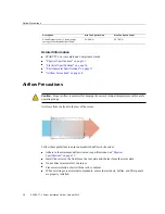
Airflow Precautions

Caution - 

Proper airflow is essential for keeping the server's internal temperatures within a safe

operating range.

Air flows from the front to the rear of the server.

Follow these guidelines to ensure unrestricted airflow in the server:

Adhere to the minimum airflow clearance specifications. See 

“Physical

Specifications” on page 15

.

Install the server so the front faces the cool aisle and the rear faces the warm aisle.

Do not direct warm air into the server.

Prevent recirculation of air within a rack or cabinet.

When servicing server internal components, ensure that air ducts, baffles, and filler panels

are properly installed.

18

SPARC T7-1 Server Installation Guide • October 2015

Summary of Contents for SPARC T7-1

Page 1: ...SPARC T7 1 Server Installation Guide Part No E54979 01 October 2015 ...

Page 2: ......

Page 3: ...us applications including applications that may create a risk of personal injury If you use this software or hardware in dangerous applications then you shall be responsible to take all appropriate fail safe backup redundancy and other measures to ensure its safe use Oracle Corporation and its affiliates disclaim any liability for any damages caused by use of this software or hardware in dangerous...

Page 4: ...ns à risque notamment dans des applications pouvant causer des dommages corporels Si vous utilisez ce logiciel ou matériel dans le cadre d applications dangereuses il est de votre responsabilité de prendre toutes les mesures de secours de sauvegarde de redondance et autres mesures nécessaires à son utilisation dans des conditions optimales de sécurité Oracle Corporation et ses affiliés déclinent t...

Page 5: ...lectrical Specifications 16 Environmental Specifications 17 Airflow Precautions 18 Preparing for Installation 21 Shipping Kit 21 Handling Precautions 23 ESD Precautions 23 Tools Needed for Installation 24 Installing the Server 25 Optional Components 25 Rack Compatibility 26 Rack Cautions 27 Stabilize the Rack 28 Install the Rackmount Hardware 29 Attach Slide Rail Assemblies to the Rack 31 Install ...

Page 6: ...ata Cables 62 Secure Cables to the CMA 62 Powering On the Server for the First Time 65 Prepare the Power Cords 66 Connect a Terminal or Emulator to the SER MGT Port 67 Oracle ILOM System Console 68 Power on the System for the First Time 69 Installing the OS 71 Configure the Preinstalled OS 71 Reach a State to Install a Fresh OS Oracle ILOM CLI 72 Reach a State to Install a Fresh OS Oracle ILOM Web...

Page 7: ... Experience with the Oracle Solaris OS troubleshooting and replacing hardware Product Documentation Library Late breaking information and known issues for this product are included in the documentation library at http www oracle com goto t7 1 docs Feedback Provide feedback about this documentation at http www oracle com goto docfeedback Using This Documentation 7 ...

Page 8: ...8 SPARC T7 1 Server Installation Guide October 2015 ...

Page 9: ...nfigure the server Step Description Links 1 Review the SPARC T7 1 Server Product Notes for any late breaking news about the server SPARC T7 1 Server Product Notes 2 Review the server features specifications and site requirements Server Overview on page 10 Confirming Specifications on page 15 3 Confirm that you received all of the items you ordered Shipping Kit on page 21 4 Learn the server feature...

Page 10: ...r cords to the server configure the Oracle ILOM on the SP power on the server for the first time and set up the operating system Powering On the Server for the First Time on page 65 Related Information SPARC T7 1 Server Product Notes SPARC T7 1 Server Safety and Compliance Guide SPARC T7 Series Servers Administration Guide SPARC T7 1 Server Service Manual Server Overview This topic provides a high...

Page 11: ...ATA drive on the front of the server above the right drive bays USB ports Two external USB 3 0 ports rear panel Two external USB 2 0 ports front panel Video port One high density DB 15 video port rear Ethernet ports Four 10GbE 100 1000 10000 Mbps RJ 45 based ports on the rear panel Power supplies Two hot swappable 1 1 AC 1000W power supplies Cooling fans Four hot swappable redundant fan modules at...

Page 12: ...er 3 Power LED green 4 Power button 5 SP Power OK button green 6 Server serial number 7 Drive 0 8 Drive 1 9 Drive 2 or NVMe drive 0 10 Drive 3 or NVMe drive 1 11 Drive 4 or NVMe drive 2 12 Drive 5 or NVMe drive 3 13 Drive 6 14 Drive 7 15 DVD drive SATA 16 Fan Fault LED amber 17 PS fault LED amber 12 SPARC T7 1 Server Installation Guide October 2015 ...

Page 13: ...mponents Installation on page 13 Cabling Requirements on page 51 Rear Panel Components Installation Note You must follow the proper sequence when connecting cables to the server Do not connect the power cords until all data cables have been connected No Description 1 Power supply 0 PS 0 2 Power supply 1 PS 1 3 PCIe slot 1 4 PCIe slot 2 Understanding the Server 13 ...

Page 14: ... connectors 2 9 SER MGT RJ 45 network port 10 NET MGT RJ 45 network port 11 PCIe slot 4 12 PCIe slot 5 13 PCIe slot 6 Related Information Front Panel Components Installation on page 12 Cabling Requirements on page 51 Attach the CMA to the Server on page 41 Secure Cables to the CMA on page 62 14 SPARC T7 1 Server Installation Guide October 2015 ...

Page 15: ...ted Information Server Overview on page 10 Shipping Kit on page 21 Identifying Ports on page 52 Physical Specifications Description U S Metric Rack units 2U 2U Height 3 45 in 87 6 mm Width 17 5 in 445 mm Depth 29 in 737 mm Weight without rackmount kit 56 lb 25 6 kg Minimum service clearance front 48 5 in 1232 mm Minimum service clearance rear 36 in 914 4 mm Minimum airflow clearance front 2 in 50 ...

Page 16: ...1306W Conforms to SpecJBB Peak AC power minimum configuration 634W Conforms to SpecJBB Maximum heat dissipation 4456 BTU hr 4702 KJ hr The maximum operating input current values are based on P V 0 90 where P max operating input power V input voltage Example 620W 120 0 90 6 89A You can use this equation to calculate your maximum operating current at your input voltage Maximum server configuration s...

Page 17: ... 35 C at 900m 40 to 149 F at 0 to 3000 ft 40 to 65 C at 900m Decrease in maximum temperature above 3000 ft 900m 1 8 F 1000 ft 1 C 300m Relative humidity 10 to 90 at 81 F 10 to 90 at 27 C Up to 93 at 100 F Up to 93 at 38 C Maximum wet bulb noncondensing Altitude 0 to 9840 ft at 95 F 0 m to 3000m at 40 C Up to 39 370 ft Up to 12 000m Except in China markets where regulations might limit installation...

Page 18: ...eping the server s internal temperatures within a safe operating range Air flows from the front to the rear of the server Follow these guidelines to ensure unrestricted airflow in the server Adhere to the minimum airflow clearance specifications See Physical Specifications on page 15 Install the server so the front faces the cool aisle and the rear faces the warm aisle Do not direct warm air into ...

Page 19: ...ables so they do not interfere with airflow Related Information Rack Cautions on page 27 Physical Specifications on page 15 Electrical Specifications on page 16 Environmental Specifications on page 17 Confirming Specifications 19 ...

Page 20: ...20 SPARC T7 1 Server Installation Guide October 2015 ...

Page 21: ...at you have the correct tools Tools Needed for Installation on page 24 Related Information Installing the Server on page 25 Connecting Cables on page 51 Powering On the Server for the First Time on page 65 Shipping Kit Note When you receive your server place it in the environment where you will install it Leave it in its shipping crate at its final destination for 24 hours This resting period prev...

Page 22: ...cords Note The shipping kit might also contain PCIe fillers that were removed from the server when PCIe cards were installed in the factory Save these PCIe fillers and use them to cover PCIe slots when cards are removed from the server Related Information Server Overview on page 10 Preparing for Installation on page 21 22 SPARC T7 1 Server Installation Guide October 2015 ...

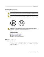
Page 23: ...pleting a two person procedure always communicate your intentions clearly before during and after each step to minimize confusion Related Information Physical Specifications on page 15 Installing the Server on page 25 SPARC T7 1 Server Getting Started Guide ESD Precautions Electronic equipment is susceptible to damage by static electricity Use a grounded antistatic wrist strap foot strap or equiva...

Page 24: ... strap connected to a metal surface on the chassis when you work on server components Related Information Handling Precautions on page 23 Tools Needed for Installation No 2 Phillips screwdriver ESD mat and grounding strap In addition you must provide a system console device such as one of the following ASCII terminal Workstation Terminal server Patch panel connected to a terminal server Related In...

Page 25: ...e that the rack does not tip when the server is installed Stabilize the Rack on page 28 5 Prepare the slide rails mounting brackets and slide rail assemblies for server installation Install the Rackmount Hardware on page 29 Attach Slide Rail Assemblies to the Rack on page 31 6 Install the server in the rack Install the Server Into the Slide Rail Assemblies on page 35 7 Optional Install the CMA Att...

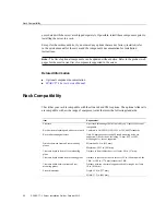
Page 26: ...tandards Item Requirement Structure 4 post rack mounting at both front and rear 2 post racks are not compatible Rack horizontal opening and unit vertical pitch Conforms to ANSI EIA 310 D 1992 or IEC 60927 standards Rack rail mounting hole sizes Only 9 5 mm square hole and M6 round mounting holes are supported All other sizes including 7 2 mm M5 or 10 32 mounting holes are not supported Distance be...

Page 27: ...mperature Tma specified for the server Caution Reduced Air Flow Install the equipment in a rack so that the amount of air flow is adequate for the safe operation of the equipment Caution Mechanical Loading Mount the equipment in the rack so that the weight is distributed evenly A hazardous condition can exist with uneven mechanical loading Caution Circuit Overloading Do not overload the power supp...

Page 28: ...before installing the server Refer to the rack documentation for detailed instructions for the following steps 1 Read the rack cautions and stabilize the rack See Rack Cautions on page 27 2 Open and remove the front and rear doors from the rack 3 To prevent the rack cabinet from tipping during the installation stabilize the cabinet using all antitilt mechanisms provided 4 If there are leveling fee...

Page 29: ...the slide rail assemblies before installation 1 Unpack the slide rails The rackmount kit contains two slide rails two mounting brackets and optional securing screws Note Refer to the rackmount kit installation card for simplified instructions about installing your server into a 4 post rack using the slide rail and CMA options No Description 1 Slide rails 2 Mounting brackets 3 Four M4 x 5 fine pitc...

Page 30: ...nings on the mounting bracket are aligned with the five locating pins on the side of the chassis No Description 1 Server front 2 Slide rail lock 3 Mounting bracket 4 Mounting bracket clip 3 With the heads of the five chassis locating pins protruding through the five keyhole openings in the mounting bracket pull the mounting bracket toward 30 SPARC T7 1 Server Installation Guide October 2015 ...

Page 31: ...o the Rack on page 31 Related Information Attach Slide Rail Assemblies to the Rack on page 31 Attach Slide Rail Assemblies to the Rack Use the rackmount installation card to identify the correct mounting holes for the slide rails Note Load the rack from bottom to top 1 Unpack the mounting brackets and installation card from the rackmount kit See Install the Rackmount Hardware on page 29 2 Ensure t...

Page 32: ...the card corresponds to the bottom edge of the server Measure up from the bottom of the installation card 4 Mark the mounting holes for the front slide rails 5 Mark the mounting holes for the rear slide rails 32 SPARC T7 1 Server Installation Guide October 2015 ...

Page 33: ...ail Assemblies to the Rack 6 Orient the slide rail assembly so that the ball bearing track is forward and locked in place No Description 1 Slide rail 2 Ball bearing track 3 Locking mechanism Installing the Server 33 ...

Page 34: ...bly against the outside of the front rack rail and push until the assembly locks into place with an audible click 9 Optional If you chose to secure the slide rail assembly to the rack with screws insert M6 mounting screws through both front and rear slide rail brackets and rack posts and then secure the screws to the rack posts with the caged nuts 10 Repeat this procedure to attach the slide rail ...

Page 35: ...at are mounted to the rack Caution This procedure requires a minimum of two people because of the weight of the server Attempting this procedure alone could result in equipment damage or personal injury Caution Always load equipment into a rack from the bottom up so that the rack does not become top heavy and tip over Extend the rack s antitilt bar to prevent the rack from tipping during equipment...

Page 36: ...es or 30 cm No Description 1 Inserting mounting bracket into slide rail 2 Slide rail release lever 5 Simultaneously pull down and hold the slide rail release levers on each mounting bracket while you push the server into the rack Continue pushing the server into the rack until the slide rail locks on the front of the mounting brackets engage the slide rail assemblies 36 SPARC T7 1 Server Installat...

Page 37: ...e engaged with the mounting brackets before you install the optional CMA 6 Optional Attach the CMA See Prepare the CMA for Installation on page 38 If you are not using the CMA see Verify Operation of Slide Rails and CMA on page 47 Related Information Prepare the CMA for Installation on page 38 Attach the CMA to the Server on page 41 Verify Operation of Slide Rails and CMA on page 47 Installing the...

Page 38: ...nstallation at the rear of the server 1 Install the server in the rack before attaching the CMA See Install the Server Into the Slide Rail Assemblies on page 35 2 Unpack the CMA The following figure shows the CMA components No Description 1 Connector A 2 Front slide bar 38 SPARC T7 1 Server Installation Guide October 2015 ...

Page 39: ...d cable covers Note The CMA ships with three flat cable covers installed Before installing the CMA you must replace the flat cable covers with the round cable covers If the round cable covers are already on the CMA skip the next step 4 If needed Remove the flat cable covers and install the round cable covers To remove the flat cable covers and install the round cable covers perform these steps a L...

Page 40: ...r comes off the hinge panel 3 c Repeat Step 4a and Step 4b to remove all three cable covers d One at a time position each round cable cover horizontally over the hinges and align the hinge connectors with the hinges e Using your thumb apply downward pressure on each hinge connector to snap the hinge connector into place f Swing the cable covers down and press down on the cable cover handle to lock...

Page 41: ...er ensure that the correct cable covers are installed on the CMA 1 Prepare the CMA for installation on the server See Prepare the CMA for Installation on page 38 2 To make it easier to install the CMA extend the server approximately 13 cm 5 inches out of the front of the rack 3 Take the CMA to the back of the equipment rack and ensure that you have adequate room to work at the back of the server N...

Page 42: ...de of the front slide bar to verify that connector A is properly seated 5 Install the CMA s connector B into the right slide rail a Insert the CMA s connector B into the front slot on the right slide rail until it locks into place with an audible click panels 1 and 2 The connector B tab goes into the slide rail s front slot panel 1 42 SPARC T7 1 Server Installation Guide October 2015 ...

Page 43: ...y tug on the right side of the front slide bar to verify that connector B is properly seated No Description 1 Connector B tab 2 Right slide rail front slot 6 Install the CMA s connector C into the right slide rail Installing the Server 43 ...

Page 44: ...nel 1 No Description 1 Connector C locking spring b Insert connector C into the right slide rail until it locks into place with an audible click panels 2 and 3 c Gently tug on the right side of the CMA s rear slide bar to verify that connector C is properly seated 7 Prepare the CMA s connector D for installation 44 SPARC T7 1 Server Installation Guide October 2015 ...

Page 45: ... s connector D into the left slide rail a While holding the slide rail latching bracket in place insert connector D and its associated slide rail latching bracket into the left slide rail until connector D locks into place with an audible click panels 1 and 2 Note When inserting connector D into the slide rail the preferred and easier method is to install connector D and the latching bracket as on...

Page 46: ... green release tab This tab is used to release and remove the latching bracket so that you can remove connector D 10 Gently tug on the four CMA connection points to ensure that the CMA connectors are fully seated before you allow the CMA to hang by its own weight 11 Verify that the slide rails and CMA operate properly See Verify Operation of Slide Rails and CMA on page 47 Related Information Prepa...

Page 47: ... to move the server in and out of the rack and one to observe the cables and CMA 1 Slowly pull the server out of the rack until the slide rails reach their stops 2 Inspect the attached cables for any binding or kinks 3 Verify that the CMA extends fully from the slide rails 4 Push the server back into the rack Installing the Server 47 ...

Page 48: ...The server slides in approximately 18 inches 46 cm and stop Verify that the cables and the CMA retract without binding before you continue b The second set of stops are the slide rail release buttons located near the front of each mounting bracket Simultaneously push both of the green slide rail release buttons and push the server completely into the rack until both slide rail locks engage 5 Adjus...

Page 49: ...Verify Operation of Slide Rails and CMA Secure Cables to the CMA on page 62 Installing the Server 49 ...

Page 50: ...50 SPARC T7 1 Server Installation Guide October 2015 ...

Page 51: ...ables Connecting Data and Management Cables on page 58 4 Secure the cables to the CMA Secure Cables to the CMA on page 62 Verify Operation of Slide Rails and CMA on page 47 Related Information Rear Panel Components Installation on page 13 Installing the Server on page 25 Powering On the Server for the First Time on page 65 Cabling Requirements Prior to cabling and powering on the server gather the...

Page 52: ...iptions of the ports Rear Panel Components Installation on page 13 USB Ports on page 52 SER MGT Port on page 53 NET MGT Port on page 54 Gigabit Ethernet Ports on page 55 VGA Port on page 56 SAS Ports on page 57 Related Information Server Overview on page 10 Front Panel Components Installation on page 12 Rear Panel Components Installation on page 13 Cabling Requirements on page 51 USB Ports Two USB...

Page 53: ...evices per server No Description 1 5V supply 2 Data 3 Data 4 Ground Related Information Server Overview on page 10 Front Panel Components Installation on page 12 Rear Panel Components Installation on page 13 Cabling Requirements on page 51 SER MGT Port The SER MGT RJ 45 port located on the rear panel provides a TIA EIA 232 serial Oracle Cisco standard connection to the SP This port is the default ...

Page 54: ...he SER MGT Port on page 67 NET MGT Port The NET MGT RJ 45 port located on the rear panel provides an optional Ethernet connection to the SP The NET MGT port is an optional connection to Oracle ILOM on the SP The SP NET MGT port uses an RJ 45 cable for a 10 100BASE T connection If your network does not use a DHCP server this port will not be available until you configure network settings through th...

Page 55: ...et Ports Four RJ 45 Ethernet ports NET 0 NET 1 NET 2 NET 3 can be accessed from the rear panel See Rear Panel Components Installation on page 13 The Ethernet interfaces operate at 100 Mbps 1000 Mbps and 10000 Mbps Pin Signal Description Pin Signal Description 1 Transmit Receive Data 0 5 Transmit Receive Data 2 2 Transmit Receive Data 0 6 Transmit Receive Data 1 3 Transmit Receive Data 1 7 Transmit...

Page 56: ... connect between the monitor and the VGA port should not be over 6 meters Pin Signal Description Pin Signal Description 1 Red Video 9 KEY 2 Green Video 10 Sync Ground 3 Blue Video 11 Monitor ID Bit 1 4 Monitor ID Bit 2 12 VGA 12C Serial Data 5 Ground 13 Horizontal Sync 6 Red Ground 14 Vertical Sync 7 Green Ground 15 VGA 12C Serial Clock 8 Blue Ground Related Information Front Panel Components Inst...

Page 57: ...mate S2 TX S3 TX Transmit from PHY to hard drive S4 Gnd Second mate S5 RX S6 RX Receive from hard drive to PHY Signal segment S1 to S7 S7 Gnd Second mate S8 Gnd Second mate S9 S10 S11 Gnd Second mate S12 S13 Back side signal S8 to S14 S14 Gnd Second mate P1 3 3V Not Supported P2 3 3V Not Supported P3 3 3V Not Supported P4 Gnd First mate P5 Gnd Second mate P6 Gnd Second mate P7 5 0V Pre charge seco...

Page 58: ...r the First Time on page 65 before connecting the AC power cords Connect the SER MGT Cable on page 58 Connect the NET MGT Cable on page 60 Connect Ethernet Network Cables on page 61 Connect Other Data Cables on page 62 Related Information Front Panel Components Installation on page 12 Rear Panel Components Installation on page 13 Cabling Requirements on page 51 Identifying Ports on page 52 Connect...

Page 59: ...cable from the SER MGT port to a terminal device When connecting a DB 9 cable use an adapter to perform the crossovers given for each connector Related Information Connect the NET MGT Cable on page 60 Connect a Terminal or Emulator to the SER MGT Port on page 67 SER MGT Port on page 53 Connecting Cables 59 ...

Page 60: ... connect to the SP using an SSH connection If your network does not use DHCP this NET MGT port is not accessible until you configure the network settings through the SER MGT port For instructions see Assign a Static IP Address to the NET MGT Port on page 77 Connect a Category 5 or better RJ 45 cable from the NET MGT port to your network switch or hub Related Information Connect Ethernet Network Ca...

Page 61: ...ernet Network Cables on page 61 Note The Oracle ILOM sideband management feature enables you to access the SP using one of these Ethernet ports Refer to Connecting to the SP In band in SPARC T7 Series Servers Administration Guide Note To achieve 1GbE network speeds use Category 6 or better cables and network devices that support 1000BASE T networks 1 Connect a Category 5 or better cable from your ...

Page 62: ...If your server configuration includes optional PCIe cards connect the appropriate I O cables to their connectors Refer to the PCIe card documentation for specific instructions Related Information PCIe card documentation SPARC T7 1 Server Service Manual Secure Cables to the CMA After connecting the server cables secure them to the CMA if a CMA was installed 1 Attach the CMA to the server in the rac...

Page 63: ...e cables to the CMA by closing the covers and tightening the straps 5 Verify the operation of the slide rails and CMA See Verify Operation of Slide Rails and CMA on page 47 Related Information Attach the CMA to the Server on page 41 Verify Operation of Slide Rails and CMA on page 47 Rear Panel Components Installation on page 13 Connecting Cables 63 ...

Page 64: ...64 SPARC T7 1 Server Installation Guide October 2015 ...

Page 65: ...Configure the Preinstalled OS on page 71 4 Configure the preinstalled OS or install a fresh OS Configure the Preinstalled OS on page 71 or Reach a State to Install a Fresh OS Oracle ILOM Web Interface on page 74 5 Set the configuration parameters for the Oracle Solaris OS Oracle Solaris OS Configuration Parameters on page 76 6 Optional Configure the NET MGT port to use a static IP address Assign a...

Page 66: ...r supply to an external power source System messages might be lost after 60 seconds if a terminal or terminal emulator is not connected to the SER MGT port before power is applied Note Oracle ILOM signals a fault if both power supplies are not cabled at the same time since it will be a nonredundant condition Do not be concerned with this fault in this situation 1 Route the power cords from the AC ...

Page 67: ...a Completed the preparation for installation See Preparing for Installation on page 21 b Completed the installation of the server in a rack See Installing the Server on page 25 c Connected the necessary cables See Connecting Cables on page 51 2 Connect a terminal or a terminal emulator PC or workstation to the server SER MGT port 3 Configure a terminal or terminal emulator with these settings 9600...

Page 68: ...lluminate After a few minutes the SP login prompt is displayed on the terminal device At this time the host is not initialized or powered on 7 Continue with the installation by powering on the server for the first time See Powering On the Server for the First Time on page 65 Related Information Connect the SER MGT Cable on page 58 Configure the Preinstalled OS on page 71 Reach a State to Install a...

Page 69: ...page 72 Reach a State to Install a Fresh OS Oracle ILOM Web Interface on page 74 Assign a Static IP Address to the NET MGT Port on page 77 Power on the System for the First Time 1 Connect a terminal device to the server s SER MGT port See Connect a Terminal or Emulator to the SER MGT Port on page 67 2 At the terminal device log in to the SP login root Password changeme After a brief delay the Orac...

Page 70: ...ght take several minutes to complete To cancel the initialization press the Hash Dot keys to return to the Oracle ILOM prompt Then type stop System 4 Optional Redirect the host output to display on the serial terminal device start HOST console Are you sure you want to start SP console y n y Serial console started 5 Optional Execute other Oracle ILOM commands while the server initializes a To displ...

Page 71: ...rmation Oracle Solaris OS Configuration Parameters on page 76 Configure the Preinstalled OS 1 Determine which OS you will use If you plan to use the preinstalled OS proceed to step 2 If you do not plan to use the preinstalled OS go to Reach a State to Install a Fresh OS Oracle ILOM CLI on page 72 or Reach a State to Install a Fresh OS Oracle ILOM Web Interface on page 74 2 When prompted follow the...

Page 72: ...S use this procedure to prevent the server from booting from the preinstalled OS 1 Prepare the appropriate boot media according to your installation method There are many methods by which you can install the OS For example you can boot and install the OS from DVD media or from another server on the network For more information about the methods refer to Installing Oracle Solaris 11 Systems compari...

Page 73: ...oot kernel default or other file Examples boot boot kernel from default device Factory default is to boot from DISK if present otherwise from NET boot net boot kernel from network boot cdrom boot kernel from CD ROM boot disk1 h boot from disk1 partition h boot tape boot default file from tape boot disk myunix as boot myunix from disk with flags as dload filename addr debug load of file over networ...

Page 74: ...o access the Oracle ILOM web interface on the server a In a browser on the same network as the system type the IP address b Log in to Oracle ILOM by typing your user name and password 3 In the Oracle ILOM web interface in the left navigation pane choose Host Management Host Boot Mode The Host Boot Mode page is displayed 4 Apply these changes to the Host Boot Mode Settings a For State select Reset ...

Page 75: ...mpt type 0 ok help boot boot specifier boot kernel default or other file Examples boot boot kernel from default device Factory default is to boot from DISK if present otherwise from NET boot net boot kernel from network boot cdrom boot kernel from CD ROM boot disk1 h boot from disk1 partition h boot tape boot default file from tape boot disk myunix as boot myunix from disk with flags as dload file...

Page 76: ...IPv6 Specify whether or not to use IPv6 If you are not sure select No to configure the Ethernet interface for IPv4 Security Policy Select either standard UNIX security No or Kerberos Security Yes If you are not sure select No Confirm Review the onscreen information and change it if needed Otherwise continue Name Service Select the name service according to your network environment If you select a ...

Page 77: ...ort If you are not already connected through the SER MGT port perform steps as needed in Connect a Terminal or Emulator to the SER MGT Port on page 67 2 Set the SP to accept a static IP address set SP network pendingipdiscovery static Set pendingipdiscovery to static 3 Set the IP address for the SP To change the default IPv4 DHCP property and set property values for a static IPv4 address type IPv4...

Page 78: ...s xxx xxx xxx xxx ipdiscovery dhcp ipgateway xxx xxx xxx xxx ipnetmask 255 255 255 0 macaddress xx xx xx xx xx xx managementport MGMT outofbandmacaddress xx xx xx xx xx xx pendingipaddress service processor IPaddr pendingipdiscovery static pendingipgateway gateway IPaddr pendingipnetmask 255 255 255 0 pendingmanagementport MGMT sidebandmacaddress xx xx xx xx xx xx state enabled 7 Set the changes t...

Page 79: ...solve an issue before you re even aware that a problem exists Oracle products with Oracle ASR securely transport electronic fault telemetry data to Oracle automatically to help expedite the diagnostic process The one way event notification requires no incoming Internet connections or remote access mechanism Only the information needed to solve a problem is communicated to Oracle Oracle ASR is a fe...

Page 80: ... com cd E37710_01 index htm How to Approve Pending ASR Assets In My Oracle Support DOC ID 1329200 1 https support oracle com rs type doc id 1329200 1 Related Information Oracle Auto Service Request Documentation http docs oracle com cd E37710_01 index htm 80 SPARC T7 1 Server Installation Guide October 2015 ...

Page 81: ...HCP Dynamic Host Configuration Protocol DTE Data terminal equipment E EIA Electronics Industries Alliance ESD Electrostatic discharge H host The part of the server or server module with the CPU and other hardware that runs the Oracle Solaris OS and other applications The term host is used to distinguish the primary computer from the SP See SP Glossary 81 ...

Page 82: ... LwA Sound power level M MAC Machine access code MAC address Media access controller address N NET MGT Network management port An Ethernet port on the server SP NVMe Nonvolatile memory express controller The optional NVMe switch card provides NVMe services in the server O Oracle ILOM Oracle Integrated Lights Out Manager Oracle ILOM firmware is preinstalled on a variety of Oracle systems Oracle ILO...

Page 83: ... MGT port Serial management port A serial port on the server SP SFF Small form factor SP Service processor In the server the SP is a card with its own OS that is operating and accessible whenever the server power cords are connected and energized regardless of host power state The SP processes Oracle ILOM commands providing lights out management control of the host Seehost SPM Service processor mo...

Page 84: ...84 SPARC T7 1 Server Installation Guide October 2015 ...

Page 85: ...R MGT port 58 clearance service 15 CMA cable strap 41 installing 41 installing on server 38 mounting bracket 41 securing cables 62 slide rail connector 41 configuring information required 51 Oracle Solaris 76 confirming specifications 15 cooling fans 10 CPU description 10 current specifications 16 D depth specification 15 DHCP servers 60 DIMM description 10 drives 10 DVD drive 10 E electrical spec...

Page 86: ... 10 mounting brackets release button 29 N NET MGT port cabling 60 DHCP 60 location 13 pinouts 54 static IP address 60 netmask 51 O optional components installation instructions 25 Oracle Auto Service Request 79 Oracle ILOM 68 Oracle Solaris configuration parameters 76 configuring the preinstalled OS 71 installing a fresh OS Oracle ILOM CLI 72 installing a fresh OS Oracle ILOM web interface 74 Over...

Page 87: ...S SAS connector pinouts 57 SER MGT port cabling 58 initial power on 67 pinouts 53 serial terminal settings 67 server overview 9 Server OK LED 12 service clearance 15 service processor show command 77 Service Required LED 12 shipping kit contents 21 show SP network command 77 show command 77 sideband management 61 site planning specifications 15 slide rail lock 29 release 29 slide rail assemblies d...

Page 88: ...ts 52 rear 13 V vibration specifications 17 video connector 10 location 13 pinouts 56 video port 10 voltage specifications 16 W weight specification 15 width specification 15 88 SPARC T7 1 Server Installation Guide October 2015 ...

Reviews: