Servicing Fan Modules (CRU)
114
Sun Server X4-4 Service Manual • October 2015
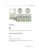
OK to Remove Indicator
Blue indicator. Indicates that the storage drive can be removed safely during a hot-service
operation.
Service Action Required Indicator
Amber indicator. Indicates that the storage drive is faulty. The front and back panel Service
Action Required indicators are also lit if the system detects a storage drive fault.
OK/Activity Indicator
Green indicator. Indicates that the drive is properly inserted into the system. Indicator flashes
when the drive is being accessed.
See Also
:
■
“Servicing Storage Drives (CRU)” on page 109
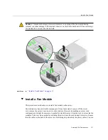
Servicing Fan Modules (CRU)
Use the following procedures to remove and install fan modules from the server:
■
“Remove a Fan Module” on page 115
■
“Install a Fan Module” on page 117
■
Summary of Contents for Sun Server X4-4
Page 1: ...Part No E38221 05 October 2015 Sun Server X4 4 Service Manual ...
Page 2: ......
Page 10: ...10 Sun Server X4 4 Service Manual October 2015 ...
Page 14: ...14 Sun Server X4 4 Service Manual October 2015 ...
Page 16: ...16 Sun Server X4 4 Service Manual October 2015 ...
Page 64: ...64 Sun Server X4 4 Service Manual October 2015 ...
Page 88: ...88 Sun Server X4 4 Service Manual October 2015 ...
Page 280: ...280 Sun Server X4 4 Service Manual October 2015 ...
Page 284: ...284 Sun Server X4 4 Service Manual October 2015 ...
Page 292: ...292 Sun Server X4 4 Service Manual October 2015 ...


