Server Block Diagram
Fan Module Redundancy
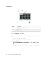
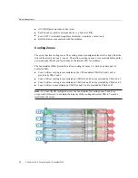
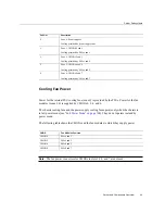
The eight fan modules (FMs) provide airflow for chassis cooling zones 1-4. For redundancy,
each zone has two dedicated FMs. If an FM fails, replace it immediately. The FMs are hot-
serviceable.
Caution -
Data Loss. Do not remove more than one fan module from a column while the system
is in full power mode. This action removes power from the CMODs and causes an immediate
shutdown. On an eight-CMOD system, this applies to all fan modules. On a four-CMOD
system, this applies to the fan modules in the left-hand fan frame (CMODs 0-3).
For FM reference and servicing information, see
“Servicing Fan Modules and Fan
Power Subsystem
Chassis power is provided by four hot-serviceable front-side accessible power supply units
(PSUs). The four PSUs provide dual (2+2) redundancy. Therefore, the minimum PSU
configuration is two. To ensure redundancy, power for the server should come from at least two
separate circuits.
When the AC power cords are connected to AC inputs at the back of the chassis, the PSUs
supply power to the Ethernet ports, the system sensors and inventory circuits, and the service
processor (SP). When power is supplied to the SP, it boots, and the server enters the low-power
standby power mode.
Once the SP boots into standby power mode, full power mode is initiated by pressing and
releasing the chassis front-panel Power button or by powering on the server remotely from
Oracle ILOM.
For more information about power modes, see
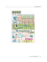
Server Block Diagram
The following illustration shows the a block diagram of the server interconnects between the
CMODs, the midplane, and the SMOD. It also shows the interconnects between attached and
integrated components:
50
Sun Server X4-8 Service Manual • December 2015
Summary of Contents for SUN X4-8
Page 1: ...Sun Server X4 8 Service Manual Part No E40317 07 December 2015 ...
Page 2: ......
Page 10: ...10 Sun Server X4 8 Service Manual December 2015 ...
Page 14: ...14 Sun Server X4 8 Service Manual December 2015 ...
Page 16: ...16 Sun Server X4 8 Service Manual December 2015 ...
Page 18: ...18 Sun Server X4 8 Service Manual December 2015 ...
Page 51: ...Server Block Diagram Server and Components Overview 51 ...
Page 52: ...52 Sun Server X4 8 Service Manual December 2015 ...
Page 78: ...78 Sun Server X4 8 Service Manual December 2015 ...
Page 228: ...228 Sun Server X4 8 Service Manual December 2015 ...
Page 236: ...BIOS Setup Utility Screens 236 Sun Server X4 8 Service Manual December 2015 ...
Page 237: ...BIOS Setup Utility Screens BIOS Setup Utility 237 ...
Page 245: ...BIOS Setup Utility Screens BIOS Setup Utility 245 ...
Page 247: ...BIOS Setup Utility Screens Memory Configuration BIOS Setup Utility 247 ...
Page 249: ...BIOS Setup Utility Screens Advanced Serial Port Console Redirection BIOS Setup Utility 249 ...
Page 250: ...BIOS Setup Utility Screens 250 Sun Server X4 8 Service Manual December 2015 ...
Page 251: ...BIOS Setup Utility Screens BIOS Setup Utility 251 ...
Page 252: ...BIOS Setup Utility Screens 252 Sun Server X4 8 Service Manual December 2015 ...
Page 253: ...BIOS Setup Utility Screens Advanced Trusted Computing BIOS Setup Utility 253 ...
Page 254: ...BIOS Setup Utility Screens 254 Sun Server X4 8 Service Manual December 2015 ...
Page 255: ...BIOS Setup Utility Screens Advanced Network Stack BIOS Setup Utility 255 ...
Page 257: ...BIOS Setup Utility Screens Advanced BMC Network Configuration BIOS Setup Utility 257 ...
Page 258: ...BIOS Setup Utility Screens 258 Sun Server X4 8 Service Manual December 2015 ...
Page 259: ...BIOS Setup Utility Screens BIOS Setup Utility 259 ...
Page 263: ...BIOS Setup Utility Screens BIOS Setup Utility 263 ...
Page 264: ...BIOS Setup Utility Screens 264 Sun Server X4 8 Service Manual December 2015 ...
Page 265: ...BIOS Setup Utility Screens BIOS Setup Utility 265 ...
Page 268: ...268 Sun Server X4 8 Service Manual December 2015 ...
Page 274: ...274 Sun Server X4 8 Service Manual December 2015 ...

