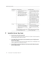
Install the Server Top Cover
Filler Panel Type
Removal Procedure
Installation Procedure
Storage drive
1. Locate the storage drive filler panel to be
removed from the server.
2. To unlatch the storage drive filler panel,
pull the release lever, and then tilt the
lever out into a fully opened position.
3. To remove the filler panel from the slot,
hold the opened release lever, and gently
slide the filler panel toward you.
1. Locate the vacant storage drive module
slot in the server, and then ensure that the
release lever on the filler panel is fully
opened.
2. Slide the filler panel into the vacant slot
by pressing the middle of the filler panel
faceplate with your thumb or finger.
3. The release lever will close as it makes
contact with the chassis. Do not slide the
filler panel in all the way. Leave the filler
panel out approximately 0.25 to 0.50 inch
(6 to 12 mm) from the opening.
4. Using your thumb or finger, press on the
middle of the filler panel faceplate until
the release lever engages with the chassis.
5. Close the release lever until it clicks into
place and is flush with the front of the
server
PCIe slot
1. Remove the server top cover.
2. To remove the PCIe slot filler panel, rotate
the PCIe locking mechanism, and then
lift and remove the PCIe slot filler panel
from the location into which you intend to
install the PCIe card.
Note -
In single-processor systems, PCIe slot
1 is nonfunctional; therefore, there is no need
to remove the filler panel for slot 1.
1. Remove the server top cover.
2. To install the PCIe slot filler panel, press
the PCIe filler panel into the vacant PCIe
slot, and then rotate the PCIe locking
mechanism to secure the PCIe slot filler
panel.
Note -
In single-processor systems, PCIe slot
1 is nonfunctional; therefore, the server ships
with this filler panel installed.
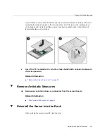
Install the Server Top Cover
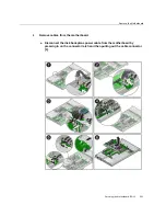
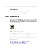
1.
Place the top cover on the chassis [1].
Set the cover down so that it hangs over the back of the server by about 1 inch (25 mm) and the
side latches align with the cutouts in the chassis.
2.
Check both sides of the chassis to ensure that the top cover is fully down and
flush with the chassis.
If the cover is not fully down and flush with the chassis, slide the cover towards the back of the
chassis to position the cover in the correct position.
3.
Gently slide the cover toward the front of the chassis until it latches into place
with an audible click [2].
210
Oracle Server X7-2 Service Manual • October 2017
Summary of Contents for X7-2
Page 1: ...Oracle Server X7 2 Service Manual Part No E72445 03 October 2017 ...
Page 2: ......
Page 14: ...14 Oracle Server X7 2 Service Manual October 2017 ...
Page 86: ...86 Oracle Server X7 2 Service Manual October 2017 ...
Page 96: ...96 Oracle Server X7 2 Service Manual October 2017 ...
Page 110: ...110 Oracle Server X7 2 Service Manual October 2017 ...
Page 136: ...136 Oracle Server X7 2 Service Manual October 2017 ...
Page 150: ...150 Oracle Server X7 2 Service Manual October 2017 ...
Page 162: ...162 Oracle Server X7 2 Service Manual October 2017 ...
Page 168: ...168 Oracle Server X7 2 Service Manual October 2017 ...
Page 178: ...178 Oracle Server X7 2 Service Manual October 2017 ...
Page 184: ...184 Oracle Server X7 2 Service Manual October 2017 ...
Page 192: ...192 Oracle Server X7 2 Service Manual October 2017 ...
Page 216: ...216 Oracle Server X7 2 Service Manual October 2017 ...
Page 252: ...252 Oracle Server X7 2 Service Manual October 2017 ...
Page 282: ...282 Oracle Server X7 2 Service Manual October 2017 ...
Page 306: ...306 Oracle Server X7 2 Service Manual October 2017 ...

