Wiring
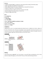
Connect the servos (Aileron, Elevator, Rudder) to the pins AIL 1 (AIL 2 is reversed direction of AIL 1), ELEV,
RUDD accordingly. When connecting, you should pay attention to the colors of wires to avoid plugging in
reversed. The WHITE (or YELLOW) signals wires should be connected corresponding to the inner pins on
the unit, the RED (VCC) wires to the center pins, and the BLACK (GND) wires to the pins on the outer edge
of the unit.
Gyro Gain Adjustment
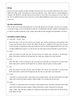
This unit has three trimmer potentiometers to control the gyro gain of roll, pitch, and yaw. Turn clockwise
to increase the gain, or turn anticlockwise to decrease. The adjustment becomes effective immediately and
no need to re-‐power up. [Note: For your safety, please DO NOT adjusting gain while propellers in motion.]
6P Switches Control Setting
1)
AUX_CTRL control Gyro
With this switch in the left side (near the pin sockets), gyro function will be always ON and AUX_CTRL
control Gyro function will be turned OFF. When this switch is switched to the right side, the gyro
function will be controlled by the AUX signal. With this function, the AUX signal within 1.7ms and 2.1ms
period will disable Gyro function, in other words, any other signal value will activate the Gyro function.
2)
RUD
With this switch in the left side (near the pin sockets), the rudder servo will work in normal mode.
When this switch is switched to the right side, the rudder servo will work in reversed mode.
3)
ELE
With this switch in the left side (near the pin sockets), the elevator servo will work in normal mode.
When this switch is switched to the right side, the elevator servo will work in reversed mode.
4)
AIL
With this switch in the left side (near the pin sockets), the aileron servo will work in normal mode.
When this switch is switched to the right side, the aileron servo will work in reversed mode.
5)
V-‐tail
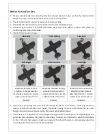
This switch is used to select the unit working in V-‐tail airplane mode. Just switch the switch to the right
side and the V-‐tail mode will be selected. LED2 will flash in a 1sec ON and 1sec OFF cycle.
6)
Delta
This switch is used to select the unit working in Delta airplane mode. Just switch the switch to the right
side and the Delta mode will be selected. LED2 will be flash in a 0.3sec ON and 2.7sec OFF cycle.
(Note: if both V-‐tail and Delta switches are selected or unselected, unit will function in Normal mode.
LED2 will be lit solid.)


