OPTIMOD-FM DIGITAL
OPERATION
3-59
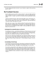
lation) by 3 dB, set the
MULTIPLEX
POWER
THRESHOLD
to “+3.”
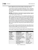
Audio Processing and the Multiplex Power Threshold Control
The multiplex power controller reduces multiplex power by applying gain reduction
before the Optimod’s FM peak limiting, thereby reducing the drive into the clippers.
With no power control, some of the louder 8300 presets can exceed the ITU stan-
dard by as much as 9 dB. This means that the clipper drive must be reduced by as
much as 9 dB, and this will vary according to the dynamics and spectral content of
the input program material. To prevent unnatural loudness variations, your Optimod
applies a static loss (set by the
M
PX
P
OWER
O
FFSET
control) when the multiplex
power controller is activated. This complements the dynamic gain reduction pro-
duced by the multiplex power controller. See the notes on the
M
PX
P
OWER
O
FFSET
control on page 3-35.
The multiplex power controller is operational with all of the Two-Band and Five-
Band processing structures.
It is not operational in Test mode and will not prevent
the 8300’s test oscillator from producing illegal modulation.
It is the responsibility of
the operator to make sure that the test oscillator does not violate the ITU require-
ments. (To ensure this, never modulate the carrier with a single L+R tone that pro-
duces total carrier modulation, including pilot tone, of more than 24%.)
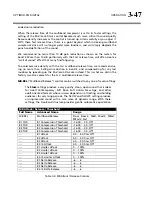
Setup: Test
Parameter
Labels
Units
Default
Range (CCW to CW)
Step
MODE ---
Operate
Operate,
Bypass,
Tone
---
BYPASS GAIN
dB
0.0
18 … +25
1
TONE FREQ
Hz
400
16, 20, 25, 31.5, 40, 50,
63, 80, 100, 125, 160,
200, 250, 315, 400, 500,
630, 800, 1000, 1250, 1600,
2000, 2500, 3150, 4000, 5000,
6300, 8000, 9500, 10000,
12500, 13586.76, 15000
LOG
TONE LVL
%
91
0 … 121
1
TONE CHAN
---
L+R
L+R, L
R, LEFT; RIGHT
---
PILOT ---
ON
ON,
OFF
---
Table 3-11: Test Modes
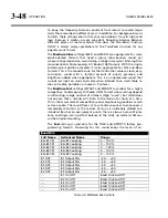
Test Modes
The Test Modes
screen allows you to switch between
O
PERATE
,
B
YPASS
,
and
T
ONE
.
When you switch to
B
YPASS
or
T
ONE
,
the preset you have on air is saved and will be
restored when you switch back to
O
PERATE
.
Table 3-11: Test Modes on page 3-59 shows the facilities available, which should be
self-explanatory.
Summary of Contents for 8300J
Page 1: ...Operating Manual OPTIMOD FM 8300 Digital Audio Processor Version 2 1 Software...
Page 7: ...Operating Manual OPTIMOD FM 8300 Digital Audio Processor Version 2 1 Software...
Page 24: ......
Page 94: ...2 46 INSTALLATION ORBAN MODEL 8300 This page intentionally left blank...
Page 190: ......
Page 204: ......
Page 246: ......
Page 247: ...OPTIMOD FM DIGITAL TECHNICAL DATA 6 29...
Page 254: ...6 36 TECHNICAL DATA ORBAN MODEL 8300 CPU Module...
Page 260: ...6 42 TECHNICAL DATA ORBAN MODEL 8300 8300 RS232 BOARD PARTS LOCATOR...
Page 262: ...6 44 TECHNICAL DATA ORBAN MODEL 8300 8300 POWER SUPPLY PARTS LOCATOR...
Page 264: ...6 46 TECHNICAL DATA ORBAN MODEL 8300 8300 I O BOARD PARTS LOCATOR...
Page 270: ...6 52 TECHNICAL DATA ORBAN MODEL 8300 DSP BOARD PARTS LOCATOR DRAWING 32170 000 14...
Page 278: ...6 60 TECHNICAL DATA ORBAN MODEL 8300 8300 DISPLAY BOARD PARTS LOCATOR...
Page 279: ...OPTIMOD FM DIGITAL TECHNICAL DATA 6 61 DISPLAY BOARD...

