1-18
INTRODUCTION ORBAN
MODEL
9400
HF Shelf Breakpoint Frequency for L+R [
L+R
HF
FR
]
HF Shelf Breakpoint Frequency for L–R [
L–R
HF
FR
]
HF Delay equalization for L+R [
L+R
HF
]
HF Delay equalization for L–R [
L–R
HF
]
Transmission Presets also contain the following controls:
System Lowpass Filter Cutoff Frequency [
LOW
PASS
]
System Lowpass Filter Cutoff Shape [
LPF
SHAPE]
System Highpass Filter Cutoff Frequency [
HIGH
PASS
]
Positive Peak Threshold (Asymmetry) [
POS
PEAK
]
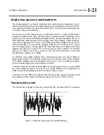
The transmitter equalizer operates in sum-and-difference mode, recognizing the
fact that, in CQUAM stereo, the envelope modulation is equal to the sum signal.
Hence, the sum (L+R) equalizer has all four controls available, while the difference
(L–R) equalizer offers only the HF shelf and HF delay adjustments. We assumed that
the L–R path (through the AM stereo exciter) would have no appreciable tilt, while
the L+R path (through the transmitter’s modulator) could suffer from tilt.
During mono operation, the L–R signal is zero and the L–R transmitter equalizer
controls have no effect.
For convenience, and to describe their most common application, the four transmit-
ter equalizer presets are labeled TX1/DAY, TX1/NIGHT, TX2/DAY, and TX2/NIGHT, al-
though they can be applied in a completely general way to the requirements of
your transmission facility.
For example, in countries observing NRSC standards you might want to transmit the
full 9.5 kHz bandwidth during the day, and, in cooperation with other stations on
first-adjacent channels, reduce audio bandwidth to 5 kHz at night. This will elimi-
nate any skywave-induced monkey-chatter interference between first-adjacent
channels. Alternatively, your nighttime directional antenna array might have poor
VSWR performance at high modulating frequencies, so you might find that your
transmitter works better and produces less distortion if you limit the audio band-
width to those frequencies where the antenna is well behaved. Further, if you oper-
ate a talk format during certain parts of the day, you will probably find that you can
operate the processing for a louder on-air sound if you restrict the transmitted
bandwidth below the maximum permitted by government regulation. (Bear in mind
that most AM radios have an audio bandwidth of 2.5-3 kHz and changing transmis-
sion bandwidth from 5 kHz to 9.5 kHz will produce virtually no audible difference
on these radios.)
Summary of Contents for Optimod-AM 9400
Page 1: ...Operating Manual OPTIMOD AM 9400 Digital Audio Processor Version 1 2 Software...
Page 7: ...Operating Manual OPTIMOD AM 9400 Digital Audio Processor Version 1 2 Software...
Page 52: ......
Page 204: ......
Page 232: ......
Page 260: ......
Page 261: ...OPTIMOD AM DIGITAL TECHNICAL DATA 6 29...
Page 267: ...OPTIMOD AM DIGITAL TECHNICAL DATA 6 35 CPU Module...
Page 273: ...OPTIMOD AM DIGITAL TECHNICAL DATA 6 41 RS232 BOARD PARTS LOCATOR...
Page 275: ...OPTIMOD AM DIGITAL TECHNICAL DATA 6 43 8300 POWER SUPPLY PARTS LOCATOR...
Page 284: ...6 52 TECHNICAL DATA ORBAN MODEL 9400 DSP BOARD PARTS LOCATOR DRAWING 32170 000 14...
Page 292: ...6 60 TECHNICAL DATA ORBAN MODEL 9400 DISPLAY BOARD PARTS LOCATOR...
Page 293: ...OPTIMOD AM DIGITAL TECHNICAL DATA 6 61 DISPLAY BOARD...

