OPTIMOD-AM DIGITAL
INTRODUCTION
1-21
Studio Line-up Levels and Headroom
The studio engineer is primarily concerned with calibrating the equipment to pro-
vide the required input level for proper operation of each device, and so that all de-
vices operate with the same input and output levels. This facilitates patching devices
in and out without recalibration.
For line-up, the studio engineer uses a calibration tone at a studio standard level,
commonly called line-up level, reference level, or operating level. Metering at the
studio is by a VU meter or PPM (Peak Program Meter). As discussed above, the VU or
PPM indication under-indicates the true peak level. Most modern studio audio de-
vices have a clipping level of no less than +21dBu, and often +24dBu or more. So the
studio standardizes on a maximum program indication on the meter that is lower
than the clipping level, so those peaks that the meter does not indicate will not be
clipped. Line-up level is usually at this same maximum meter indication. In facilities
that use VU meters, this level is usually at 0VU, which corresponds to the studio
standard level, typ4 or +8dBu.
For facilities using +4dBu standard level, instantaneous peaks can reach +18dBu or
higher (particularly if the operator overdrives the console or desk). Older facilities
with +8dBu standard level and equipment that clips at +18 or +21dBu will experi-
ence noticeable clipping on some program material.
In facilities that use the BBC-standard PPM, maximum program level is usually PPM4
for music, PPM6 for speech. Line-up level is usually PPM4, which corresponds to
+4dBu. Instantaneous peaks will reach +17dBu or more on voice.
In facilities that use PPMs that indicate level directly in dBu, maximum program and
line-up level is often +6dBu. Instantaneous peaks will reach +11dBu or more.
Transmission Levels
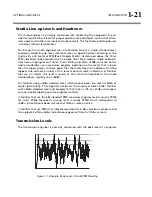
The transmission engineer is primarily concerned with the peak level of a program
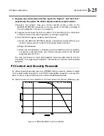
ABSOLUTE PEAK
PPM
VU
Figure 1-1: Absolute Peak Level, VU and PPM Reading
Summary of Contents for Optimod-AM 9400
Page 1: ...Operating Manual OPTIMOD AM 9400 Digital Audio Processor Version 1 2 Software...
Page 7: ...Operating Manual OPTIMOD AM 9400 Digital Audio Processor Version 1 2 Software...
Page 52: ......
Page 204: ......
Page 232: ......
Page 260: ......
Page 261: ...OPTIMOD AM DIGITAL TECHNICAL DATA 6 29...
Page 267: ...OPTIMOD AM DIGITAL TECHNICAL DATA 6 35 CPU Module...
Page 273: ...OPTIMOD AM DIGITAL TECHNICAL DATA 6 41 RS232 BOARD PARTS LOCATOR...
Page 275: ...OPTIMOD AM DIGITAL TECHNICAL DATA 6 43 8300 POWER SUPPLY PARTS LOCATOR...
Page 284: ...6 52 TECHNICAL DATA ORBAN MODEL 9400 DSP BOARD PARTS LOCATOR DRAWING 32170 000 14...
Page 292: ...6 60 TECHNICAL DATA ORBAN MODEL 9400 DISPLAY BOARD PARTS LOCATOR...
Page 293: ...OPTIMOD AM DIGITAL TECHNICAL DATA 6 61 DISPLAY BOARD...

