2-2
INSTALLATION ORBAN
MODEL
9400
2.
Check the line voltage, fuse and power cord.
DO NOT connect power to the unit yet!
A)
Check the
V
OLTAGE
S
ELECT
switch. This is on the rear panel.
The 9400 is shipped from the factory with the
V
OLTAGE
S
ELECT
switch set
to the 230V position. Check and set the
V
OLTAGE
S
ELECT
switch to your
local voltage requirements. To change the operating voltage, set the
V
OLTAGE
S
ELECT
to 115V (for 90-130V) or 230V (for 200-250V) as appro-
priate.
B)
Install the proper fuse and fuse holder, per your country’s standards.
The 9400 is shipped from the factory with the fuse, and fuse holder re-
moved. Select the appropriate fuse holder and fuse from the supplied
parts in the accessory kit. Use the gray fuse holder for domestic / 115V
operation, or the black fuse holder for European / 230V operation. For
safety, use ½-A-250V Slow-Blow for 115V, or 500mA-250V for 230V.
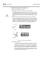
CONDUCTOR
WIRE COLOR
L
N
E
LINE
NEUTRAL
EARTH GND
BROWN
BLUE
GREEN-YELLOW
BLACK
WHITE
GREEN
NORMAL
ALT
PLUG FOR
115 VAC
(USA)
CONDUCTOR
WIRE COLOR
L
N
E
LINE
NEUTRAL
EARTH GND
BROWN
BLUE
GREEN-YELLOW
PLUG FOR
230 VAC
(EUROPEAN)
TYPE H05VV - F - 0.75
TYPE 18/3 SVT COR, TYP
(3 x .82 mm
2
)
Figure 2-1: AC Line Cord Wire Standard
C)
Check the power cord.
AC power passes through an IEC-standard mains connector and an RF fil-
ter designed to meet the standards of all international safety authorities.
The power cord is terminated in a “U-ground” plug (USA standard), or
CEE7 / 7 plug (Continental Europe), as appropriate to your 9400’s Model
Number. The green / yellow wire is connected directly to the 9400 chassis.
If you need to change the plug to meet your country’s standard and you
are qualified to do so, see Figure 2-1. Otherwise, purchase a new mains
cord with the correct line plug attached.
Summary of Contents for Optimod-AM 9400
Page 1: ...Operating Manual OPTIMOD AM 9400 Digital Audio Processor Version 1 2 Software...
Page 7: ...Operating Manual OPTIMOD AM 9400 Digital Audio Processor Version 1 2 Software...
Page 52: ......
Page 204: ......
Page 232: ......
Page 260: ......
Page 261: ...OPTIMOD AM DIGITAL TECHNICAL DATA 6 29...
Page 267: ...OPTIMOD AM DIGITAL TECHNICAL DATA 6 35 CPU Module...
Page 273: ...OPTIMOD AM DIGITAL TECHNICAL DATA 6 41 RS232 BOARD PARTS LOCATOR...
Page 275: ...OPTIMOD AM DIGITAL TECHNICAL DATA 6 43 8300 POWER SUPPLY PARTS LOCATOR...
Page 284: ...6 52 TECHNICAL DATA ORBAN MODEL 9400 DSP BOARD PARTS LOCATOR DRAWING 32170 000 14...
Page 292: ...6 60 TECHNICAL DATA ORBAN MODEL 9400 DISPLAY BOARD PARTS LOCATOR...
Page 293: ...OPTIMOD AM DIGITAL TECHNICAL DATA 6 61 DISPLAY BOARD...


