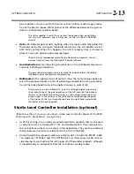
2-16
INSTALLATION ORBAN
MODEL
9400
C)
Turn off the tone by pressing the
T
ONE
button.
If the STL transmitter suffers from bounce or overshoot, you may have to
reduce the
L
O
UT
and
R
O
UT
control settings to avoid peak overmodulation
caused by overshoots on certain audio signals.
4.
Set controls for normal operation with program material.
The following assumes that a VU meter is used to determine 8200ST line drive
levels with program material.
A)
Set the controls as follows:
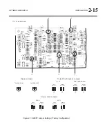
HF LIMITER... Set to match the pre-emphasis of the transmission system
L&R Out ................................................................................do not change
GATE .................................................................................................... 12:00
RELEASE ............................................................................................... 12:00
VOICE ......................................................................................................OFF
AGC ..........................................................................................................ON
COUPLE ....................................................................................................ON
B)
Feed the 8200ST either with tone at your system reference level (0VU), or with
typical program material at normal levels.
C)
Adjust the
G
AIN
R
EDUCTION
control for the desired amount of gain reduction.
We recommend 8-15 dB gain reduction for most formats.
If the STL uses pre-emphasis, its input pre-emphasis network will proba-
bly introduce overshoots that will increase peak modulation without any
increase in average modulation. We therefore strongly recommend that
the STL transmitter’s pre-emphasis be defeated (freeing the STL from
such potential overshoot), and that the 464A be used to provide the nec-
essary pre-emphasis.
If the STL transmitter’s pre-emphasis cannot be defeated, configure the
8200ST for flat output. In this case, average modulation levels of the STL
may have to be reduced to accommodate the overshoots.
Quick Setup
Quick Setup guides you through 9400 setup for your primary analog AM transmitter.
It is appropriate for users with modern transmitter plants and without special re-
quirements such as setting up HD Radio processing or CQUAM AM stereo process-
ing. Following this section, you can find more detailed information regarding setup
beyond the Quick Setup screens. In most cases, you will not need this extra informa-
tion.
Quick Setup assumes that your transmission plant does not need to use the 9400’s
Transmitter Equalizer. This should be true if you are using a modern solid-state
transmitter and have a reasonably wideband antenna system. If your plant needs to
use this to correct tilt, overshoot, or ringing in the RF envelope, then you will have
to adjust it after Quick Setup is completed.
Summary of Contents for Optimod-AM 9400
Page 1: ...Operating Manual OPTIMOD AM 9400 Digital Audio Processor Version 1 2 Software...
Page 7: ...Operating Manual OPTIMOD AM 9400 Digital Audio Processor Version 1 2 Software...
Page 52: ......
Page 204: ......
Page 232: ......
Page 260: ......
Page 261: ...OPTIMOD AM DIGITAL TECHNICAL DATA 6 29...
Page 267: ...OPTIMOD AM DIGITAL TECHNICAL DATA 6 35 CPU Module...
Page 273: ...OPTIMOD AM DIGITAL TECHNICAL DATA 6 41 RS232 BOARD PARTS LOCATOR...
Page 275: ...OPTIMOD AM DIGITAL TECHNICAL DATA 6 43 8300 POWER SUPPLY PARTS LOCATOR...
Page 284: ...6 52 TECHNICAL DATA ORBAN MODEL 9400 DSP BOARD PARTS LOCATOR DRAWING 32170 000 14...
Page 292: ...6 60 TECHNICAL DATA ORBAN MODEL 9400 DISPLAY BOARD PARTS LOCATOR...
Page 293: ...OPTIMOD AM DIGITAL TECHNICAL DATA 6 61 DISPLAY BOARD...

