OPTIMOD-PC
OPERATION
3-11
•
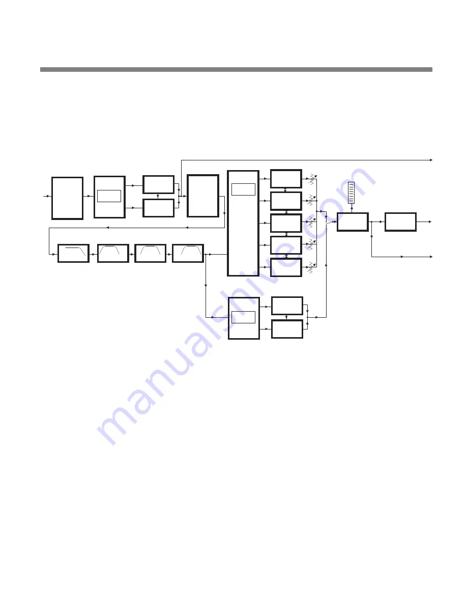
Multiband Compression
in either two or five bands, depending on the proc-
essing structure
•
Automatic Loudness Control
using Orban’s third-generation CBS Loudness
Controller™ algorithm
•
Low-IM Distortion Look-Ahead Limiting
LOOK-AHEAD
MAIN
OUT
LIMITER
LOW IM
COMPRESSOR
MASTER
MF PEAKING EQ
AGC
OUT
"PROCESSED WITHOUT LIMITING" OUT
COMPRESSOR
EQUALIZER
LF PEAKING EQ
EQUALIZER
LF SHELVING EQ
EQUALIZER
INPUT
>150Hz
CROSSOVER
<150Hz
AGC
ENHANCER
STEREO
COUPLING
BASS
2B
COUPLING
CROSSOVER
2-BAND
>200Hz
<200Hz
HF PEAKING EQ
EQUALIZER
<100Hz
<200Hz
or
100-520Hz
XOVER IN
MASTER
COMPRESSOR
COMPRESSOR
BASS
CLIPPER
+ EMBEDDED
COUPLING
CONTROLS
CONTROLS
OUTPUT MIX
COMPRESSOR
COMPRESSOR
HIGH
FREQUENCY
ENHANCER
MULTIBAND
CROSSOVER
1800-6000Hz
520-1800Hz
>6kHz
5B
COMPRESSOR
COMPRESSOR
COMPRESSOR
LOUDNESS
CONTROLLER
LOUDNESS
METER
Figure 3-2: Simplified OPTIMOD-PC Digital Signal Processing Diagram
Stereo Enhancement:
OPTIMOD-PC provides two different stereo enhancement
algorithms. The first is based on Orban’s patented analog 222 Stereo Enhancer,
which increases the energy in the stereo difference signal (L–R) whenever a transient
is detected in the stereo sum signal (L+R). By operating only on transients, the 222
increases width, brightness, and punch without unnaturally increasing reverb (which
is usually predominantly in the L–R channel).
The second stereo enhancement algorithm is based on the well-known “Max” tech-
nique. This passes the L–R signal through a delay line and adds this decorrelated sig-
nal to the unenhanced L–R signal. Gating circuitry similar to that used in the “222-
style” algorithm prevents over-enhancement and undesired enhancement on slight-
ly unbalanced mono material.
Use stereo enhancement with care if you are driving a low bitrate codec. At low bi-
trates, these codecs use various parametric techniques for encoding the spatial at-
tributes of the sound field. Stereo enhancement can unnecessarily stress this encod-
ing process.
Summary of Contents for Optimod-PC 1101
Page 4: ......
Page 14: ......
Page 121: ...OPTIMOD PC OPERATION 3 1 Section 3 Operation Figure 3 1 The OPTIMOD PC Control Application...
Page 192: ...3 72 OPERATION ORBAN MODEL 1101...
Page 204: ......
Page 210: ......
Page 212: ...5 2 UNINSTALLATION ORBAN MODEL 1101...
Page 236: ......


