background image


16 

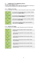
8.1.3  Calibration of Resistances


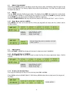
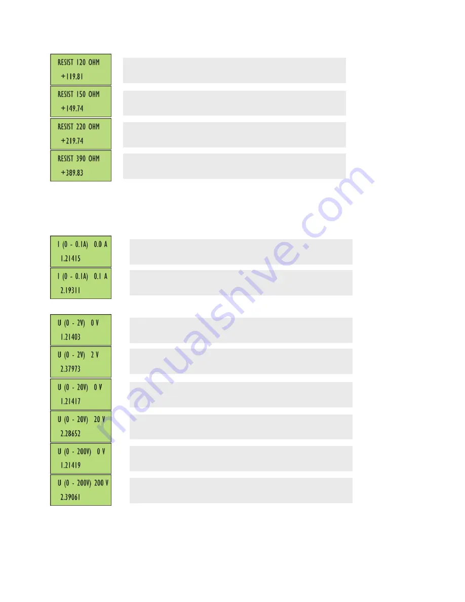
Connect Ohm-Meter to the calibrator outputs. The required accuracy is 0.05%. 


8.2 

CALIBRATION MULTIMETER 

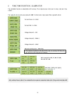
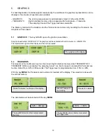
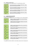
Select the required range (2) or (3). 
The Range (2) is for calibration of the current, the Range (3) is for the voltage calibration.  


The key 

ESC

 terminates the calibration and the display returns into the measuring mode. 


Set  with  the  keyboard  the  resistance  value  which  is  being 
measured with the connected Ohm-Meter.


Set  with  the  keyboard  the  resistance  value  which  is  being 
measured with the connected Ohm-Meter.


Set  with  the  keyboard  the  resistance  value  which  is  being 
measured with the connected Ohm-Meter.


Set  with  the  keyboard  the  resistance  value  which  is  being 
measured with the connected Ohm-Meter.


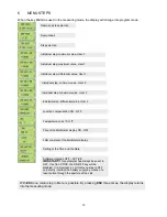
Supply from external current calibrator 0.000 mA and confirm with 
OK. The point 0.00A is calibrated.


Supply  from  external  current  calibrator  100.000  mA  and  confirm 
with OK. The point 0.1A is calibrated.


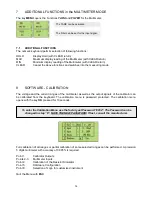
Supply  from  external  voltage  calibrator  0.000  V  and  confirm  with 
OK. The point 0V is calibrated. 


Supply from external voltage calibrator 2.000 V and confirm with 
OK. The point 2V is calibrated


Supply  from  external  voltage  calibrator  20.000  V  and  confirm  with 
OK. The point 20V is calibrated. 


Supply  from  external  voltage  calibrator  0.000  V  and  confirm  with 
OK. The point 0V is calibrated. 


Supply  from  external  voltage  calibrator  0.000  V  and  confirm  with 
OK. The point 0V is calibrated. 


.


Supply from external voltage calibrator 200.000 V and confirm with 
OK. The point 200V is calibrated. 


Summary of Contents for OC 505

Page 1: ...505_GBM_21507 CALIBRATOR MULTIMETER OC 505 Owner s Manual ORBIT CONTROLS AG Zürcherstrasse 137 CH 8952 Schlieren ZH Tel 41 44 730 2753 Fax 41 44 730 2783 e mail info orbitcontrols ch www orbitcontrols ch ...

Page 2: ...2 ...
Page 3: ... Thermocouple Connector Owner s Manual and Calibration Certificate Vor dem Einschalten ZU BEACHTEN Dieses Gerät wurde sorgfältig verpackt Falls es bei Ihnen in beschädigtem Zustand eintrifft benachrichtigen Sie unverzüglich den Orbit Controls Kundendienst Tel 41 44 730 2753 oder Fax 41 44 730 2783 und nehmen Sie einen Schadenrapport auf welchen Sie auch von der Transportgesellschaft unterschreiben...

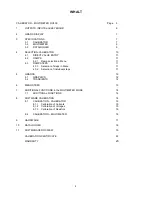
Page 4: ...election of steps in Menu 11 4 3 2 Selection of individual steps 11 5 GRAFICS 12 5 1 GRAPHICS 12 5 2 TRANSIENTS 12 6 MENU STEPS 13 7 ADDITIONAL FUNCTIONS in the MULTIMETER MODE 14 7 1 ADDITIONAL FUNCTIONS 14 8 SOFTWARE CALIBRATION 14 8 1 CALIBRATION CALIBRATOR 15 8 1 1 Calibration of Currents 15 8 1 2 Calibration of Voltages 15 8 1 3 Calibration of Resistors 16 8 2 CALIBRATION MULTIMETER 16 9 HARD...

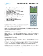
Page 5: ...tters and small signal inputs with resolution of up to 0 001mV Thermocouples J K N R S T B E are simulated The temperature is entered with the keyboard and shown at the display The cold junction is compensated to the ambient temperature It can also be switched off RTD Thermometers can be simulated within the DIN temperature range The temperature is entered with the keyboard and shown at the displa...

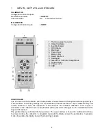
Page 6: ... The software calibration of all ranges is accessible in the calibration menu and protected with a password All ranges can be recalibrated via the keyboard if required The graphic display is divided into two windows The upper window is shows the multimeter functions the lower window the calibrator In programming mode the display shows the parameters In graphics mode of operation the display shows ...

Page 7: ...rger 3 SPECIFICATIONS 3 1 CALIBRATOR Voltage and Current OUTPUT Thermocouples Cu Connector Conversion 16 Bit Current Source Range 0 22mA Maximum external Shunt 750 Ohm Accuracy 0 05 from Value 0 1 from Range Resolution 0 001 mA Current Sink Range 0 22mA at 24V maximum Accuracy 0 05 from Value 0 1 from Range Resolution 0 001 mA Voltage Source Range 0 25 V 0 560mV 0 28mV Accuracy 0 05 from Value 0 1...

Page 8: ...arger Mains Voltage100 240V 48 60Hz 12V 600mA DC Charging time 4 hours The batteries are fully charged when the green LED illuminates continuously Cabinet Dimensions 200 x 90 x 40mm L x W x D weight 320 g R Range C 50 0 0 400 400 1760 Accuracy C 1 6 1 6 1 6 S Range C 50 0 0 500 500 1760 Accuracy C 2 4 1 9 1 5 B Range C 50 800 800 100 1000 1820 Accuracy C 2 5 1 5 1 3 J Range C 140 0 0 700 700 1200 ...

Page 9: ... to a Windows PC Two Set Points LEVEL LOW and LEVEL HIGH and two Intervals INTERVAL 1 and INTERVAL 2 will be selected If the measured signal is between the both Set Points LEVEL LOW and LEVEL HIGH the data will be stored with INTERVAL 1 The INTERVAL 2 stores the date when the input signal is outside the Set Points The both Intervals can be selected from 2 sec to 24 hours With the key LOGG is the f...

Page 10: ...ource 0 22mA Current Sink 0 22mA Voltage Output 0 25V Voltage Output 0 560mV Voltage Output 0 28mV Resistance Output 45 3000 Ohm RTD Outputs Pt 100 Pt 200 Pt 500 Pt 1000 Ni 1000 Simulation of Thermocouples B J K N R S T OK confirms the selection The selected function remains memorised also when the power is switched off If the resistance is measured with external Ohm meter the polarity of the Ohm ...

Page 11: ...ps selection in MENU Press MENU The step can be selected from firmly pre programmed values with the vertical cursors Confirm with OK 4 3 RAMP STEPS With keys RAMP or STEP the display will increment in steps selected in the MENU 4 3 1 Selection of Steps in the MENU Press the key MENU Use the vertical cursors to select the Step from pre programmed values Confirm with OK 4 3 2 Selection of individual...

Page 12: ...ted with vertical cursors GRAPH ON The latest stored signal will be displayed when OK is pressed 5 2 TRANSIENTS Fast signals at the multimeter input can be stored Eight individual memory slots TRANSIENT NO 1 TRANSIENT NO 8 are available The sampling rate is 1ms Each transient contains 256 Point and can be time limited from 0 25 to 300 seconds The Trigger level is programmable from 10 to 90 With th...

Page 13: ...r 2 Junction compensation ON OFF Temperature units ºC or ºF Tare of the Multimeter display ON OFF Filter constant of the Multimeter display Setting of the Time and the Date Software Upgrade OFF ACTIVE IMPORTANT This parameter has always been set to OFF If set to ACTIVE the ON OFF key will be disabled It is important to set this menu step to OFF and shortly interrupt the battery supply by means of ...

Page 14: ... calibrator can be calibrated from the keyboard The calibration menu is password protected The calibration menu opens with the key OK pressed for 10 seconds Full calibration of all ranges or partial calibration of some selected ranges can be performed A precision 5 digits multimeter with accuracy of 0 005 is required Point 1 Calibrator Outputs Points 2 3 Multimeter Inputs Point 4 Calibration of th...

Page 15: ... the value with the keyboard until the connected mA Meter shows 20 000 mA SOURCE MODUS Set the value with the keyboard until the connected mA Meter shows 4 000 mA SINK MODUS Set the value with the keyboard until the connected mA Meter shows 20 000 mA SINK MODUS Set the value with the keyboard until the connected V Meter shows 0 000 V Set the value with the keyboard until the connected V Meter show...

Page 16: ...oard the resistance value which is being measured with the connected Ohm Meter Supply from external current calibrator 0 000 mA and confirm with OK The point 0 00A is calibrated Supply from external current calibrator 100 000 mA and confirm with OK The point 0 1A is calibrated Supply from external voltage calibrator 0 000 V and confirm with OK The point 0V is calibrated Supply from external voltag...

Page 17: ... have been done or the calibration incorrect terminated The menu steps contain Correction of the junction temperature Battery charge display correction Restore of factory calibration values Backup of new calibration values Standard instruments are 0 20mA The output option 100 00mA has to be ordered at the factory The temperature of the output terminals will be measured with external thermometer Th...

Page 18: ...VAL 2 The Intervals are programmable from 2 seconds to 24 hours DATA STORE After LEVEL LOW and LEVEL HIGH and INTERVAL 1 and INTERVAL 2 are set the data logging can be initiated with LOGGER ON and OK In the menu step LOGGER OFF is the logging terminated Beginning of the storing is announced with a beep tone During the storing period the display shows STO changing with The key MENU and the vertical...

Page 19: ...ger OC505W will be installed at the PC and opened The window shows the selection Select COM in the Menu Window COM The data port will be automatically found with Find COM The Lamp changes the colour to green when the communication is running Assure the speed of the PC COM to run at high Baud Rate Default Pass Default Password is 8952 and will be transferred to OC505 An individual password previous...

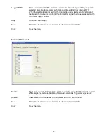
Page 20: ...nal has to be measured at the multimeter input 100mA Stop Communication stops Save The data are stored in a Text Format txt or Excel Format xls Copy Copy the data Transient Data Table Number Eight memory slots for fast signals at the multimeter input Each Transient contains 256 samples selectable Sampling Time and selectable Trigger Level see 5 2 Upload The selected Transiente will be transferred ...

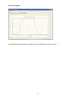
Page 21: ...21 Transient Graphics The selected Transient appears as Graphics with Time Base Scale Date and Time ...

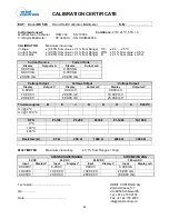
Page 22: ...age Output Voltage Output Voltage Output Display Output V Display Output mV Display Output mV 0 000 V 0 00 mV 0 000 mV 10 000 V 200 00 mV 10 000 mV 20 000 V 500 00 mV 25 000 mV Thermocouples B E J K N R S T 300ºC mV 0 ºC mV 1000 ºC MULTIMETER Maximum inaccuracy 0 1 from Range 1 Digit SPANNUNGSEINGANG STROMEINGANG 2V DC 20V DC 200V DC 100 mA DC Input Display V Input Display V Input Display V Input ...

Page 23: ... will be pleased to answer all your questions not only to this instrument but also to all our calibrators and measuring equipment Please call our customer service or write to us info orbitcontrols ch Thank you Orbit Controls AG Customer Service Zürcherstrasse 137 Tel 41 44 730 2753 8952 Schlieren Zürich Fax 41 44 730 2783 Switzerland www orbitcontrols ch info orbitcontrols ch PLEASE NOTE The instr...

Reviews: