background image

10

  |  USER GUIDE

 OMR 700

CONNECTION 
OF THE INSTRUMENT

3.

OUT.2

  8x Relay, switch-on contact

OUT.1

  4x Relay, switch-over contact

A

B

C

D

E

F

G

H

I

J

K

L

OUT.2

1

2

3

4

5

6

7

8

A

B

C

D

E

F

G

H

I

J

K

L

OUT.1

1

2

3

4

OUT.4

  16x OC, NPN

OUT.3

  8x OC, NPN

OUT.3

A

B

C

D

E

F

G

H

I

J

K

L

M

N

O

P

Q

1

2

3

4

5

6

7

8

OUT.4

A

B

C

D

E

F

G

H

I

J

K

L

M

N

O

P

Q

1

2

3

4

5

6

7

8

9

10

11

12

13

14

15

16

+

+

+

+

+

+

+

+

+

+

+

+

+

+

+

+

-

OUT.6

  6x SSR

OUT.5

  8x OC, PNP

OUT.5

A

B

C

D

E

F

G

H

I

J

K

L

M

N

O

P

Q

+

+

+

+

+

+

+

+

+

- - -

-

-

-

1

2

3

4

5

6

7

8

10...30 VDC

OUT.6

A

B

C

D

E

F

G

H

I

J

K

L

M

N

O

P

Q

1

2

3

4

5

6

Summary of Contents for OMR 700 Series

Page 1: ...OMR 700 PAPERLESS RECORDER USER GUIDE 148 9 C 263mm 453mV Outstanding Measurement Value ...

Page 2: ...safety regulations The manufacturer is not liable for damage caused by improper installation configuration maintenance and service The recorder must be installed according to the respective application Incorrect installation can cause a malfunction which can result in damage or accident The recorder uses dangerous voltages that can cause a fatal accident Before you start solving problems e g in ca...

Page 3: ...OF THE INSTRUMENT 4 3 CONNECTION OF THE INSTRUMENT 6 Instrument connection 6 Card connection 7 4 CONTROL OF THE INSTRUMENT 12 5 SETTING OF THE INSTRUMENT 14 Introduction 14 Control bar 16 First power on 20 6 TECHNICAL DATA 24 7 DIMENSIONS AND ASSEMBLY 28 8 WARRANTY CERTIFICATE 29 ...

Page 4: ...he display is multi touch and it there fore allows an ease of use Control The recorder is controlled by both the touch screen and the push buttons with adjustable functions positioned underneath a sliding front door Two LEDs indicate run error and the state of data recording Setting All functions and settings can be performed directly on the instrument s display in a clear graphical menu Data reco...

Page 5: ... card and insert it into a vacant slot In this way the instrument can grow in compliance with your requirements All analogue modules are fully isolated from the internal bus and some cards have galvanic isolation even between individual channels Basic version of the recorder includes power supply module and communication module with Ethernet 10 100 RS 485 MODBUS five digital inputs and two digital...

Page 6: ...D E F G H I J K L M N O P Q A B C D E F G H I J K L M N O P Q A B C D E F G H I J K L M N O P Q A B C D E F G H I J K L M N O P Q A B C D E F G H I J K L M N O P Q A B C D E F G H I J K L A B C D E F G H I J K L A B C D E F G H I J K L A B C D E F G H I J K L A B C Power source Firmly placed card Communication Firmly placed card B5 Card slot Ethernet RS 485 Digital inputs B4 Card slot B3 Card slot...

Page 7: ... ES 5 E E ES S S S E E ES 5 1 2 4 3 1 2 4 3 1 2 4 3 E E ES S S S E E ES 5 IN 4 4x T C nput IN 3 4x RTD input IN 03 4 OHM 0 0 1 0 3 1 3 10 30 kΩ RTD Pt 50 100 500 1 000 Cu Cu 50 100 Ni Ni 1 000 10 000 E ES S ES E ES S ES E ES S ES E ES S ES 3 A B C D E F G H I J K L M N O P Q 2 1 Shielding GND 1 GND 2 GND 3 GND 4 IN 04 4 T C J K T E B S R N L 3 A B C D E F G H I J K L M N O P Q 2 1 Shielding GND 1 ...

Page 8: ... 0 1 2 5 5 A AC U1 0 10 250 V 1 2 A B C D E F G H I J K L IN 10 3 1 2 3 1 2 3 AC U2 0 120 450 V IN 09 A B C D E F G H I J K L M N O P Q 1 Shielding GND 1 DC I 0 20 mA 4 20 mA 20 mA DC U 0 5 V 0 10 V 5 V 10 V 1 2 1 2 2 GND 2 1 2 3 GND 3 1 2 IN 12 12x Pulse input IN 11 8x Digital input A B C D E F G H I J K L Shielding IN 11 1 2 3 4 5 6 7 8 AC DC 12 250 V AC DC IN 12 A B C D E F G H I J K L M N O P ...

Page 9: ...A B C D E F G H I J K L M N O P Q 1 GND 1 GND 2 Shielding 2 1 2 1 2 3 wire LVDT sensors 1 2 5 wire LVDT sensors IN 13 A B C D E F G H I J K L M N O P Q Shielding contact 1 2 wire sensors NPN NO 2 3 wire sensors PNP NO 3 3 wire sensors PNP NO 4 1 2 3 4 Excitation GND 560 R 2W IRC sensors line NPN PNP 5 2 5 A B C A B C A B C A B C A B C 1 ...

Page 10: ...5 6 7 8 A B C D E F G H I J K L OUT 1 1 2 3 4 OUT 4 16x OC NPN OUT 3 8x OC NPN OUT 3 A B C D E F G H I J K L M N O P Q 1 2 3 4 5 6 7 8 OUT 4 A B C D E F G H I J K L M N O P Q 1 2 3 4 5 6 7 8 9 10 11 12 13 14 15 16 OUT 6 6x SSR OUT 5 8x OC PNP OUT 5 A B C D E F G H I J K L M N O P Q 1 2 3 4 5 6 7 8 10 30 VDC OUT 6 A B C D E F G H I J K L M N O P Q 1 2 3 4 5 6 ...

Page 11: ...eption transmission positive CNTR signal for repeater control DGND reference potential for data and 5 V VP 5 V A RxD TxD N data reception transmission negative Pin asignment 3 4 6 8 5 DO 2 Port 1 Port 2 AO 2 4x Analogue output AO 02 A B C D E F G H I J K L M N O P Q Analog output voltage Analog output current 1 2 1 1 2 2 1 2 3 1 2 4 1 2 Shielding EXC 1 4x Excitation EXC 1 A B C D E F G H I J K L M...

Page 12: ...and proper click of the front lid Proper snap of the front lid The lid can be opened by pressing the two blue tabs toward each other and lowering the lid with a capacity touchpanel USB USB connector for Flash drive Com MicroUSB for connection to PC SD Card Slot for SD card Rst Reset button Button 2 button function can be set in menu Button 1 button function can be set in menu Stat OK Error Rec act...

Page 13: ...ignalling during device start up Stat Rec Display Meaning off off inactive Device is not powered bliká rychle off inactive Normal state on off inactive Undervoltage processor not running bliká rychle off inactive Undervoltage processor running Signalling while device is running Stat Rec Display Meaning flashes off active Normal state flashes off active General error flashes active Recording in pro...

Page 14: ... of providing requested adjustments of the measured signals or preparation of the output values Screens graphical representation of the measured or calculated values on the recorder display Records what where how often in what format and other parameters of measured or calculated data for recording Timers provide periodic execution of linked blocks with a given period Constants spontaneously uncha...

Page 15: ...s under different phases of processing A Typeical input card provides several values for each input direct input value of the converter converter bits value converted into electrical value e g mA and the resulting converted value e g in case of weight the strain gauge input card recalculates the voltage of the strain gauge into weight by a preset formula Range tare Similarly it is possible to cont...

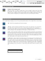
Page 16: ... Press icon to enter menu Recorder status OK Device is OK Warning Device is out of pre defined values Error Device is out of pre defined values Its functionality may be compromised Critical error Device is out of pre defined values Its functionality is compromised Recording status Recording inactive Recording in progress No errors detected Recording in progress Medium 80 full Recording in progress Me...

Page 17: ...e specified values Warning state will disappear and the log record will be carried out Error device outside the specified values but with possible consequences onitsfunctioning This state can be caused for instance by an undervoltage greater than 20 by filling the memory in excess of 90 and by many other causes At the Error state an error window is displayed through which you can view the errors I...

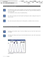
Page 18: ...ssible to switch screens in the default setting User with access rights User has the right of switching over screens viewing errors logs and memory media User with access rights Advanced user and beyond has in addition access to the menu Switching the previous or the next screen Switching over to yesther screen If you have defined only one screen the screen remains unchanged Switching over to the ...

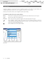
Page 19: ...USER GUIDE OMR 700 19 148 9 C 263mm 453mV 5 SETTING OF THE INSTRUMENT ...

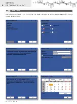
Page 20: ...E OMR 700 5 SETTING OF THE INSTRUMENT 5 3 FIRST START When you turn on the device for the first time the Guide will help you with the basic settings so that the unit is ready for further work 20 USER GUIDE OMR 700 ...

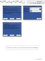
Page 21: ...USER GUIDE OMR 700 21 148 9 C 263mm 453mV 5 SETTING OF THE INSTRUMENT For detailed device settings as well as practical examples please refer to the User Guide ...

Page 22: ... lines and two buttons Name from the list of created user names kindly select the one under which you want to log in Level level of access rights of the selected user Password after a click on the line a keyboard appears Then enter the password to log in button Confirm confirms the login If the password is OK the dialogue disappears and the icon in the control bar will change If the password is in...

Page 23: ...USER GUIDE OMR 700 23 148 9 C 263mm 453mV 5 SETTING OF THE INSTRUMENT ...

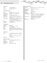
Page 24: ...communication TCP IP Modbus Wi Fi optionalmodulewithstandardorindustrialtemperature Range POWER SUPPLY Range 10 30 V AC DC 10 PF 0 4 ISTP 75 A 2 ms 80 250 V AC DC 10 PF 0 4 ISTP 45 A 2 ms isolated Power supply is protected by a fuse inside the instrument Consumption 30 VA 30 W MECHANIC PROPERTIES Material Noryl GFN2 SE1 non flammable UL 94 V I Dimensions 150 x 150 x 80mm Depth beh panel 85 mm Pane...

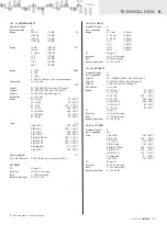
Page 25: ...ACY TC 25 ppm C Accuracy 0 15 of the range Rate 5 320 measuring s Recomm positions A1 A2 A3 A4 IN 2 4x U I INPUT Number of inputs 4 Galv separation yes Range 0 5 mA 200 mV 0 20 mA 200 mV 4 20 mA 200 mV 2 V 10 MΩ 5 V 1 25 MΩ 10 V 1 25 MΩ 40 V 1 25 MΩ TC 25 ppm C Accuracy 0 2 of the range Rate 1000 measuring s Recomm positions A1 A2 A3 A4 IN 3 4x RTD INPUT Number of inputs 4 Galv separation yes Type...

Page 26: ... range Rate 1 000 measuring s Recomm positions A1 A2 A3 A4 IN 9 3x PRECISE PM INPUT U I Number of inputs 3 Galv separation yes Range 5 mA 200 mV 20 mA 200 mV 4 20 mA 200 mV 2 V 10 MΩ 5 V 1 25 MΩ 10 V 1 25 MΩ 40 V 1 25 MΩ TC 25 ppm C Accuracy 0 02 of the range Rate 1 000 measuring s Recomm positions A1 A2 A3 A4 IN 11 8x ANALOGUE DIGITAL INPUT Number of inputs 8 Galv separation no Range 12 250 V AC ...

Page 27: ...s B2 B3 B4 B5 OUT 5 8x OPEN COLLECTORS PNP Number of outputs 8 Galv separation no Type digital menu adjustable Outputs 8x open collector PNP 30 VDC 700 mA Contact closure 0 2 ms Recomm positions B2 B3 B4 B5 OUT 6 6x SSR Number of outputs 6 Galv separation no Type digital menu adjustable Outputs 6x SSR 250 VAC 1 A Contact closure 0 2 ms Recomm positions B2 B3 B4 B5 AO 1 2x ANALOGUE OUTPUTS Number o...

Page 28: ... apply gradually all four mounting bolts with stones into rectangular holes and fix them in a clockwise direction tighten the bolts with a Phillips screwdriver Panel cut Panel thickness 0 5 8 6 26 8 mm Side view Front view 138 mm 138 mm 0 5 0 5 0 5 0 5 85 6 mm 115 9 mm 150 mm 136 7 mm 150 mm 150 mm OMR 700 1 2 ...

Page 29: ...echanic damage transportation intervention of unqualified person incl the user unavoidable ivent other unprofessional interventions The manufacturer performs guarantee and postguarantee repairs unless provided for otherwise Stamp signature WA R R A N T Y riod of 60 months from the date of sale to the user applies to this instr riod of 60 months from the date of sale to the user applies to this ins...

Page 30: ......

Page 31: ...onic measuring control and laboratory devices Requirements for EMC Industrial use EN 50131 1 chap 14 and chap 15 EN 50130 4 chap 7 EN 50130 4 chap 8 EN 61000 4 11 ed 2 EN50130 4 chap 9 EN 61000 4 2 EN 50130 4 chap 10 EN 61000 4 3 ed 2 EN 50130 4 chap 11 EN 61000 4 6 EN 50130 4 chap 12 EN 61000 4 4 ed 2 EN 50130 4 chap 13 EN 61000 4 5 EN 61000 4 8 EN 61000 4 9 EN 61000 6 1 EN 61000 6 2 EN 55022 cha...

Page 32: ...BIT MERRET spol s r o Vodňanská 675 30 198 00 Praha 9 Czech Republic tel 420 281 040 200 fax 420 281 040 299 e mail orbit merret eu www orbit merret eu TECHDOK OMR 700 2018 2v0 en WA R R A N T Y Y E A R S ...

Reviews: