USER GUIDE
OMR 700
|
11
148.9~C
-263mm
453mV
3.
CONNECTION
OF THE INSTRUMENT
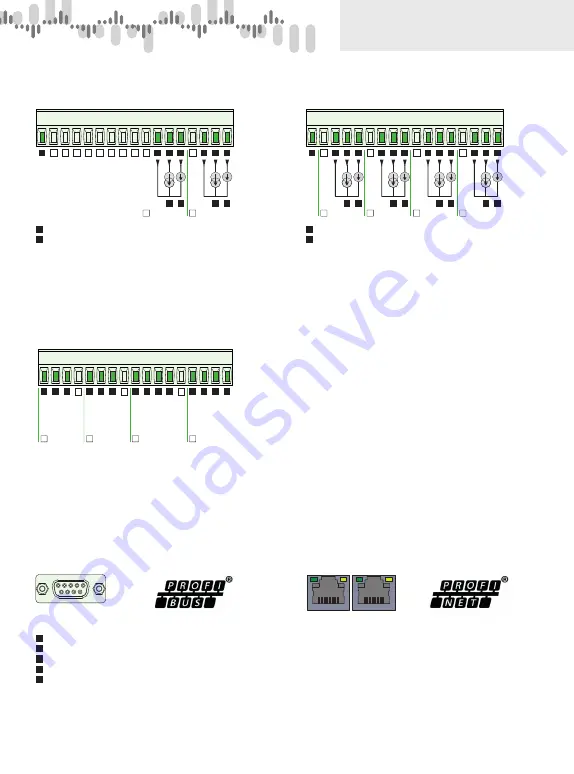
AO.1
2x Analogue output
AO.01
A
B
C
D
E
F
G
H
I
J
K
L
M
N
O
P
Q
+
+
-
Analog output - voltage
Analog output - current
1
2
1
1
2
+
+
-
2
1
2
Shielding
DO.2
1x PROFINET
DO.1
1x PROFIBUS
DO.1
1
9
5
6
B:
RxD/TxD-P data reception/transmission, positive
CNTR:
signal for repeater control
DGND:
reference potential for data and +5 V
VP:
+5 V
A:
RxD/TxD-N data reception/transmission, negative
Pin asignment
3
4
6
8
5
DO.2
Port 1
Port 2
AO.2
4x Analogue output
AO.02
A
B
C
D
E
F
G
H
I
J
K
L
M
N
O
P
Q
+
+
-
Analog output - voltage
Analog output - current
1
2
1
1
2
+
+
-
2
1
2
+
+
-
3
1
2
+
+
-
4
1
2
Shielding
EXC.1
4x Excitation
EXC.1
A
B
C
D
E
F
G
H
I
J
K
L
M
N
O
P
Q
+
+
+
+
+
+ +
+
−
1
5/ 10/ 12/ 24
VDC
5/ 10/ 12/ 24
VDC
5/ 10/ 12/ 24
VDC
5/ 10/ 12/ 24
VDC
2
3
4
− −
− −
−


