background image

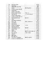
J-8 

Drilling screws 


4PCS 

Seat post 


1SET 

Seat slider assembly 


1SET 

L-1 

Screw 

M5xP0.8x12L 

2PCS 

L-2 

Cover for seat slider(R) 


1PCS 

L-3 

Seat slider 


1PCS 

L-4 

Cap for seat slider 


1PCS 

L-5 

Fixing screw bracket 

7/16"-14 

1PCS 

L-6 

Flat washer 

φ

14.3x

φ

25x2.0t 

1PCS 

L-7 

Knob for seat slider   


1PCS 

L-8 

Cover for seat slider (L) 


1PCS 

L-9 

Self-tapping screw 

M4x15L 

1PCS 

L-10 

Seat 


1PCS 

Handlebar assembly 


1SET 

M-1 

Foam grip 

550x

φ

20x5m/m 

2PCS 

M-2 

Handlebar   


1PCS 

M-3 

Hand pulse 


2PCS 

M-4 

Cap for handlebar 

φ

7/8" 

2PCS 

M-5 

Hand pulse wire 


1PCS 

M-6 

Self-tapping screw 

M4x20L 

2PCS 

M-7 

Cap for wire 


1PCS 

Tools 


1SET 

N-1 

Allen bolt 

M8xP1.25x20L(6m/m) 

8PCS 

N-2 

Flat washer 

φ

8x

φ

19x2t 

8PCS 

N-3 

Wrench 


1PCS 

N-4 

Allen Key 


1PCS 

N-5 

Box spanner 


1PCS 

N-6 

T-knob for handlebar 

M8xP1.25x65L 

1PCS 

N-7 

Cover for handlebar post   


1PCS 

Summary of Contents for OBKB01

Page 1: ...rst consulting a physician No specific health claims are made or implied as they relate to the equipment Measurements made by the equipment are believed to be accurate but only the measurements of you...

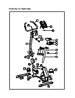
Page 2: ...L 10 K L 3 L 6 L 7 E 3 H 1 L 2 M 2 Drawing for Assembly...

Page 3: ...F 4 F 3 F 2 F 1 F 5 G 11 G 13 Exploded drawing...

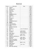
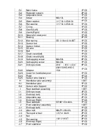
Page 4: ...for flywheel 1PCS C 13 Pulley 1PCS D Idler wheel assembly 1SET D 1 Idler set 1PCS D 2 Idler wheel 24x 37x20 5mmL 1PCS D 3 Nut 1PCS D 4 Flat washer 8 5x 25x1t 1PCS D 5 Hex Bolt M8xP1 25x20L 1PCS D 6 W...

Page 5: ...4x50L 6PCS G 20 Self tapping screw M4x30L 1PCS G 21 Drilling screws 3 16 10 x3 4 6PCS G 22 Adapter 230V 50HZ 9VDC 1 5A 1PCS G 23 Cover for handlebar post 1PCS G 24 Pedal 1PCS G 25 Sensor wire lower 1P...
Page 6: ...r seat slider L 1PCS L 9 Self tapping screw M4x15L 1PCS L 10 Seat 1PCS M Handlebar assembly 1SET M 1 Foam grip 550x 20x5m m 2PCS M 2 Handlebar 1PCS M 3 Hand pulse 2PCS M 4 Cap for handlebar 7 8 2PCS M...

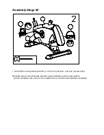
Page 7: ...16L 8 2T 8 J 7 G 1 I 5 1 Attach the front Stabilizer J 7 to the main Frame G 1 using two screws N 1 and flat washers N 2 2 Attach the rear Stabilizer I 5 to the main Frame G 1 using two screws N 1 an...

Page 8: ...1 Assemble the two pedals G 24 R L onto the Crank G 8 G 9 with a screw driver Remarks Screw the left pedal s spindle counter clockwise and the right pedal s spindle clockwise Use a wrench or screwdriv...

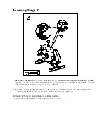
Page 9: ...using a screwdriver In addition the Slider can be adjusted in horizontal level by loosening the Knob 2 Insert the seat post K into the main frame G 1 and then choose the desired position and tighten t...

Page 10: ...8 2T 4 1 Put the cover G 23 into the Handlebar post H 1 Connect the sensor wires Upper lower H 2 G 25 2 Insert the handlebar post H 1 to the main frame with Allen bolts E 2 flat washer E 1 and semi c...

Page 11: ...Assembly Stage 5 1 M 2 M 5 H 1 1 Assembly the handlebar M 2 onto the handlebar post H 1 2 Put the cover N 7 and tighten the T knob N 6...

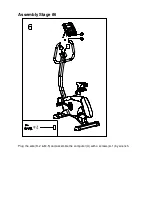
Page 12: ...Assembly Stage 6 4 M 5 Plug the wire H 2 M 5 and assemble the computer A with 4 screws A 1 by wrench...

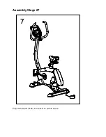
Page 13: ...Assembly Stage 7 Plug the adapter G 22 into socket as picture above...

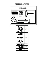
Page 14: ...er 1 Box Spanner 1 Box Spanner 1 Box Spanner 1 Allen Key 1 Allen Key 1 Allen Key 1 Allen Key 1 Screwdriver 1 DB01R N 1 Allen Bolt M8 P1 25 16L 8 N 6 T shape knob M8 65L 1 N 2 Regular Washer 8 19 2t 8...

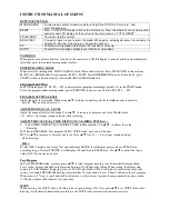
Page 15: ...can only increase to Level32 can only decrease to 1 ADJUSTING MANUAL LEVEL Adjust the manual level in start mode Press to increase or decrease one level If hold on for 1 5s will 2levels per second and...

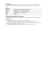
Page 16: ...ing range 0 30 230 WATT Display range 0 999 Setting range 10 350 SPEED 0 99 9KM RPM 0 999 INSPECTION FOR ABNORMAL CONDITION LCD display E 2 Inspect the electronic watch and console 5PIN connecting cab...

Reviews: