background image


Assembling Instructions


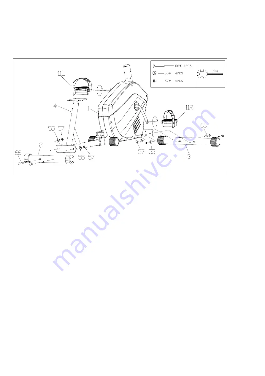
STEP 1 


--Attach  the  rear  stabilizer(2)  to  the  rear  support  rack  (4)  with  screws  (66)  ,waved 

washers (55) and cap nut

57

carefully.   

Note:  The  rear  stabilizer(2)  is  without  the  transport  wheel,  don’t  mix  with  the  front 

stabilizer 

--Attach  the  front  stabilizer(3)  to  the  main  frame(1)  with  screws  (66)  ,waved  washers 

(55) and cap nut

57

  carefully.   

--Attach the pedal (11L/R) to the crank (26) with the spanner tightly. Be sure the right 

pedal(11R) marked (R) is attached to the right crank tightly in the clockwise direction. 

The left pedal(11L) marked(L) is attached to the left crank tightly in the anticlockwise 

direction. 


Summary of Contents for OBR103

Page 1: ...MAGNETIC BIKE OWNER S MANUAL BGR103 CONTENTS IMPORTANT INFORMATION COMPLETE EXPLOSION DRAWING PARTS LIST OBR8301FC OBR8301FC OBR8301FC OBR103 OBR103 Mag Recumbent Owner s manual OBR103...

Page 2: ...ound it 4 Before starting any exercise program you must consult your doctor to determine if you have any physical or health conditions that could create a risk to your health and safety or prevent you...

Page 3: ...fective components while assembling or checking the equipment or if you hear any unusual noises coming from the equipment during use stop immediately Do not use the equipment until the problem has bee...

Page 4: ...orrectly tightened 3 Remember regularly to grease moving parts 4 Special attention to the component most of them are susceptible to wear like brake system foot pad etc 5 As sweat is very corrosive do...

Page 5: ...5 Complete Explosion Drawing...

Page 6: ...or Wire 1 56 washer 12 17 Resistance adjuster 1 57 Cap nut 6 18 Adjuster Wire bottom 1 58 Spring washer 4 19 Pulse Sensor Wire 1 59 Convenient Cover 1 20 Handle Pulse Sensor 2 60 Sensor Wire bottom 1...

Page 7: ...on t mix with the front stabilizer Attach the front stabilizer 3 to the main frame 1 with screws 66 waved washers 55 and cap nut 57 carefully Attach the pedal 11L R to the crank 26 with the spanner ti...

Page 8: ...8 STEP 2 Attach the backrest elbow tube 21 to the rear support rack 4 with screws 54 washers 56 and spring washers 58 correctly...

Page 9: ...9 STEP 3 Attach the backrest 6 and saddle 5 to the backrest elbow tube 21 with screws 54 and washers 56 carefully and tightly...

Page 10: ...10 STEP 4 Attach the rear handle bar 28 to the backrest elbow tube 21 with screws 41 and waved washers 55 tightly Connect the pulse sensor wires 19 60 correctly...

Page 11: ...r carefully Also connect the sensor wires 62 61 correctly Please ensure that all the pins are straight when connecting 17 18 14 16 and 62 61 Failure to do so will result in console malfunction Attach...

Page 12: ...y Then attach console 9 to the front post 7 with Note 1 To sure a good connection when connecting the hand pulse sensors and main console wires firmly Push all excess wires back down the stem until th...

Page 13: ...ipment is completed assembled if you find it not leveled on the floor you can adjust it by the adjusting rear stabilizer tube plug 13 Make sure you have tightened all the screws and nuts well before b...

Page 14: ...TIME DISTANCE CALORIES RESET IF HAVE The key to reset the value to zero by pressing the key OPERATION PROCEDURES 1 AUTO ON OFF The system turns on when any key is pressed or when it sensor an input f...

Page 15: ...il pointer lock on to CALORIE The calorie burned will be displayed when starting exercise 5 ODOMETER IF HAVE Press the MODE key until the pointer advance to ODOMETER The total accumulated distance wil...

Page 16: ...16...

Reviews: