OceanTRx™4-500 O3b System Installation Guide
1-1
1
1
I
I
n
n
t
t
r
r
o
o
d
d
u
u
c
c
t
t
i
i
o
o
n
n
Orbit’s O3b installation is based on OceanTRx™4-500 satellite antenna systems. The O3b
installation is designed to ensure continuous coverage through handover between
operating antennas, as well as robustness through redundancy of operating antennas and
(optionally) a backup antenna and a backup communication room.
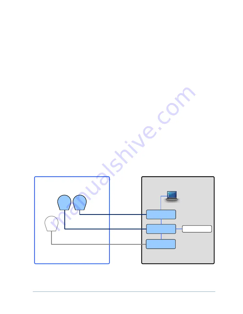
The O3b installation consists of either two or three antennas installed above deck, where
usually only two of the antennas operate at any one time - tracking or preparing to track
a satellite. A third (optional) antenna can serve as a backup antenna that (usually) tracks
the satellites as well but only begins transmitting in the event one of the operational
antennas is faulty.
Although antenna handover can be performed according to various, user defined criteria,
it is (by default) performed automatically to provide continuous coverage over the
changeover period of two satellites - one satellite descending and the other ascending, to
compensate for defined blockage zones and for a faulty antenna.
The antennas can be installed at a distance of up to 140 meters from the communication
room located below deck, where data between the antennas and communication room is
transferred over coaxial cable.
The MtsVLink, antenna dedicated management application is used for antenna setup,
management and troubleshooting operations. Once the system is installed and set up,
the O3bLink management application is used for overall system monitoring and if
necessary, for troubleshooting and re-configuration of the handover criteria.
The following figure illustrates the O3b system with three antennas (two operational and
one backup).
Above Deck Equipment
Communication Room
Satellite Modem
1
2
3
(Optional)
Backup Antenna
Operational
Antennas
OSS
(RF Switch)
CCU
(Control Unit)
O3B MNG
OSS
(RF Switch)
1-1.O3b General System Description of a System Architecture


