


General Rules:
The heating cable must be evenly distributed.
The relationship between supply voltage, linear resistance, cable
length, and center spacing are important. As they need to be understood in order to give the right operating
temperature and surface temperature distribution.
When installing, it is important to remember that all of the heating cables, including the bulb and splice to cold leads, must
be embedded so that only the non-heating lead is exposed outside of the pour. By NEC standards, a conduit is used to
bring the leads out of the pour. The heating section of the cable should not be in direct contact with any combustible
surface. This is achieved by embedding the cable in a liquid self-leveling material completely. Another option is attaching
chicken wire or diamond lathe to the sub-floor first, then tie down the cable and apply the self-leveling material
The heating section of the cable shall not touch or crossover itself. As an option, measure
and mark the center spacing within the design area as a reference for cable layout. Lay the heating cable out with the cold
leads starting at the power source. The cable must be laid at the calculated spacing. A template can be cut 1/4’’ less than
the required center spacing in order to hold true center spacing and account for the cable thickness. Cables should be
secured using approved means (See Page 1). The cables should not be left unprotected for extended periods of time as
the risk of damage increases. Concentration of heating cables around columns, drains, etc. may lead to overheating.
It is very important for the cable spacing to be held to the design
parameters in order to avoid installation problems.
(Tile
Installers Preferred Method).
Layout Restriction:
(Minimum distance between adjacent runs and minimum bending diameter is 2 inches).
Before starting to lay the cable, determine your “On Center” spacing by following the formula on the top of Page 1.
Heating cables must be installed in open areas only. The layout requires that the entire heating
cable be looped at even center spacing over the area that is to be heated. If a thermostat with floor sensor is purchased,
consider the location of the floor sensor when planning your layout. The floor sensor must be placed in between two runs of
heating cable. The end of the heating cable marked with the asterisks is terminated at a point where the power connection
is made, which is usually a thermostat or junction box. Details of cable length, loading, voltage, etc., are given on UL tag.
GENERAL INSTALLATION INFORMATION
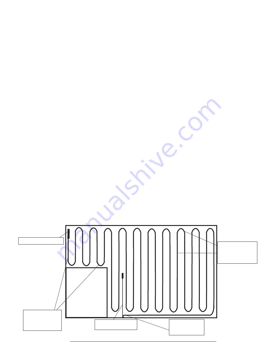
TWIN CONDUCTOR CABLE LAYOUT EXAMPLE
The actual layout of the cable is not important. However, it is recommended to run the cable across the shorter dimension
of the space. Decide where you are going to start your cable within the design area. Start by laying the cable with the
splice, making sure the word ‘SPLICE’ will be buried into the pour. Use an approved tie down method described on Page 1.
Cable tie downs should be spaced every 12 - 16 inches. Tie downs
pinch or constrict the cable in any way.
Cables should be snug, but able to move freely. Run the cable along the outside edge of the design area and any
permanent fixtures, using half the “on center” spacing (Spacing Formula on Page 1). This means if the spacing is 6” O/C ,
lay the cable 3” from the wall. (We recommend staying 8” away from toilet wax seal.) After the exterior edge is down,
proceed laying the cable in a serpentine fashion using the full O/C spacing over the balance of the open area to be warmed.
It is important to remember to maintain half the “on center” spacing dimension around the remaining outer edges of the
design area. Where multiple cables are being installed into one design, follow the layout and spacing with each cable
beginning at the power source and ending within the area to be heated. Repeat as required.
SHOULD NOT
CABLES MAY NOT BE
WIRED TOGETHER IN SERIES.
VERY IMPORTANT NOTE:
All splices must be completely buried.
Cold lead
terminates at the
power source.
Cold lead
terminates at the
power source.
End bulb of the cable
End bulb of the cable
Thermostat with
embedded floor sensor.
Maintain 1/2 the
O/C Spacing from
walls and fixed
objects.
Maintain 1/2 the
O/C Spacing from
walls and fixed
objects.
Continue using full
O/C Spacing
between all cable
runs.
Continue using full
O/C Spacing
between all cable
runs.
Cabinet


