[REV. 20200115] OW_ORBIWELD_BA_821060201_00__INH-02_EN
Orbitalum Tools GmbH
D-78224 Singen www.orbitalum.com
47
ORBIWELD 38S, 76S, 115S, 170
Set-up and assembly
ENGLISH
8.3
Mounting the clamping inserts
1. Position the weld head on the supporting area.
2. Open the swivel clamp.
3. Insert the clamping insert (2) with the writing facing
outwards. The lock (1) has to latch in.
2
1
8.4
Setting up the electrode
The weld head contains 2 electrode holes for different electrode diameters, that are identified by 2 electrode markings in the
rotor. The following steps apply for both electrode diameters.
ATTENTION!
Unintentional starting up of the weld head!
Crushing of hands and fingers.
X
Switch off the welding power supply.
NOTE!
Damage to property through electrode in the toothed space!
If the electrode projects into the toothed space, jamming can occur in the transmission.
X
Shorten the electrode.
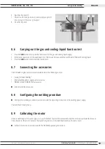
1. Insert the workpiece.
2. Press the MOTOR button and keep it pressed until the
electrode hole (2) has reached the 12 o’ clock position.
3. Check the electrode (5) for sharpness and geometry (see
4. Set the electrode distance with a feeler gage (3) and tighten
the electrode clamping screw by means of a screwdriver (1).
1
2
3
5
4


