background image

HX 12P

HX 25P

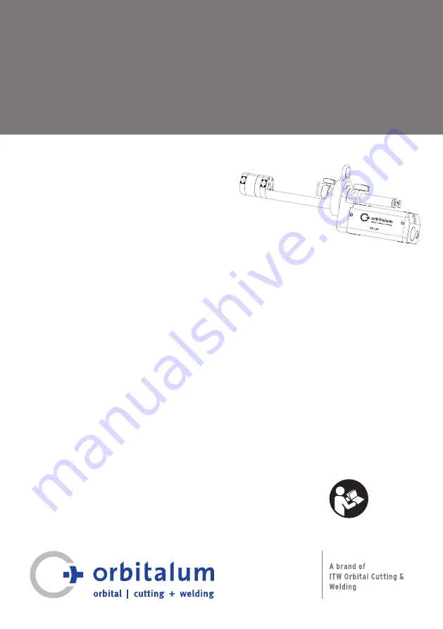
de Geschlossene Orbitalschweißköpfe

Originalbetriebsanleitung und Ersatzteilliste

en Enclosed orbital weld heads

Translation of original operating instructions  

and spare parts list

it Teste per saldatura orbitale a 

camera chiusa

Traduzione del manuale d'istruzioni originale

e elenco dei ricambi

84

7 0

60 2

01

Summary of Contents for 845 000 010

Page 1: ...triebsanleitung und Ersatzteilliste en Enclosed orbital weld heads Translation of original operating instructions and spare parts list it Teste per saldatura orbitale a camera chiusa Traduzione del manuale d istruzioni originale e elenco dei ricambi 847 060 201 ...

Page 2: ...responsible bodies and persons using the machine To ensure safe working read the operating instructions before commissioning Keep these operating instructions for future reference All rights reserved in particular the rights of duplication and distribution as well as translation en page 29 Manuale di istruzioni per titolari e personale qualificato all utilizzo delle macchine Per lavorare in sicure...

Page 3: ...7 7 Stolpern über das Schlauchpaket 10 2 7 8 Elektrischer Schlag 10 2 7 9 Augenschäden durch Strahlen 11 2 7 10 Allgemeine Verletzungen durch überstehende Teile 11 2 7 11 Gefahren durch elektromagnetische Felder 11 2 7 12 Erstickungsgefahr durch zu hohen Argonanteil in der Luft 11 2 7 13 Allgemeine Verletzungen durch Werkzeuge 11 3 Beschreibung 12 4 Einsatzmöglichkeiten 13 4 1 Typen 13 4 2 Einsätz...

Page 4: ... konfigurieren 22 8 11 Motor kalibrieren 22 9 Bedienung 23 9 1 Bedienelemente 23 9 2 Schweißparameter einstellen 23 9 3 Schweißen 24 10 Instandhaltung und Störungsbeseitigung 24 10 1 Pflegehinweise 24 10 2 Wartung und Pflege 24 10 2 1 Standard Reinigungsprozess des Schweißkopfes 25 10 3 Fehlerbehebung 27 10 4 Service Kundendienst 28 Ersatzteilliste 81 EG Konformitätserklärung 107 ...

Page 5: ...nsituation die bei Nichtbeachtung der Sicherheitsmaßnahmen zum Tod oder zu schweren Verletzungen führen kann VORSICHT Mögliche Gefahrensituation die bei Nichtbeachtung der Sicherheitsmaßnahmen zu leichten Verletzungen führen kann HINWEIS Mögliche Gefahrensituation die bei Nichtbeachtung zu Sachschäden führen kann 1 2 Weitere Symbole und Auszeichnungen KATEGORIE SYMBOL BEDEUTUNG GEBOT Dieses Symbol...

Page 6: ...eitnehmer ausgenommen solche mit aktiven Implantaten Arbeitnehmer mit aktiven Implantaten 1 2 3 Lichtbogenschweißung manuell einschl MIG Metall Inertgas MAG Metall Aktivgas WIG Wolfram Inertgas bei Einhaltung bewährter Verfahren und ohne Körperkontakt zur Leitung Nein Nein Ja Nach Richtlinie 2013 35 EU 2 2 Verwendung der Maschine 2 2 1 Bestimmungsgemäße Verwendung Die Orbitalschweißköpfe sind auss...

Page 7: ...tsorgen 2 3 2 Elektrowerkzeuge und Zubehör Ausgediente Elektrowerkzeuge und Zubehör enthalten große Mengen wertvoller Roh und Kunststoffe die einem Recyclingprozess zugeführt werden können Elektronische Altgeräte die mit dem nebenstehenden Symbol gekennzeichnet sind dürfen gemäß EU Richtlinie nicht mit dem Siedlungsabfall Hausmüll entsorgt werden Durch die aktive Nutzung der angebotenen Rückgabe u...

Page 8: ...rbitalschweißkopf nicht ändern oder umbauen X Orbitalschweißkopf nur in technisch einwandfreiem Zustand verwenden X Nur Original Werkzeuge Ersatzteile und Zubehör sowie vorgeschriebene Betriebsstoffe verwenden X Schutzeinrichtungen nicht entfernen X Bei Änderungen im Betriebsverhalten Betrieb sofort beenden und Störung beseitigen lassen 2 6 Persönliche Schutzausrüstung Folgende persönliche Schutza...

Page 9: ...hr sich an der Elektrode zu stechen X Orbitalschweißkopf nicht an der Position der Elektrode greifen X Vor dem Verstauen des Orbitalschweißkopfs im Transportkoffer Elektrode demontieren 2 7 3 Quetschung durch rotierenden Rotor VORSICHT Quetschgefahr Quetschgefahr besteht in folgenden Situationen Der Rotor fährt beim Einrichten unbeabsichtigt an Hände und Finger werden gequetscht Der Rotor wird nac...

Page 10: ... schlimmsten Fall wird ein Brand ausgelöst Allgemeine Brandschutzmaßnahmen vor Ort beachten X Schutzhandschuhe tragen X Vor Arbeiten am Orbitalschweißkopf oder vor dem Verpacken im Transportkoffer warten bis sich die Oberflächen auf unter 50 C abgekühlt haben X Formiersystem korrekt positionieren X Im Schweißbereich nur zulässige Materialien einsetzen 2 7 7 Stolpern über das Schlauchpaket VORSICHT...

Page 11: ... bringen X Vor der Inbetriebnahme prüfen ob die Druckversorgung die vorgegebenen Parameter nicht überschreitet 2 7 11 Gefahren durch elektromagnetische Felder GEFAHR Je nach Ausführung des Arbeitsplatzes können im direkten Umfeld lebensgefährliche elektro magnetische Felder entstehen X Menschen mit Herzproblemen oder Herzschrittmachen dürfen die Schweißanlage nicht bedienen X Der Betreiber hat den...

Page 12: ...ierung Position des Bogenanschlags Fixierung der stufenlosen Grobverstellung Feineinstellung des Bogenanschlag 3 Balanceröse Befestigung Schweißkopf an Rohr 4 Bedienfeld Schweißkopf bedienen 5 Typenschild Zeigt Daten zum Schweißkopf an 6 Schlauchpaket Schweißkopf mit Schweißstromquelle verbinden 7 Spanneinsatz Schweißkopf zentrieren an Rohr 8 Spannkolben Schweißkopf an Rohr klemmen 9 Rotor Elektro...

Page 13: ...e die grundsätzlich für das WIG DC Schweißverfahren geeignet sind 4 2 Einsätze 4 2 1 Spanneinsätze Aus Edelstahl Je 2 Stück Spanneinsätze werden pro Schweißkopf benötigt Spanneinsätze müssen gemäß den zu schweißenden Rohrdurchmessern gewählt werden 5 TECHNISCHE DATEN 5 1 Anwendungsbereich MASCHINENTYP HX 12P HX 25P Code 847 000 010 845 000 010 Rohr Außendurchmesser min max mm inch 9 5 13 3 0 374 0...

Page 14: ... 45 00 1 772 62 00 2 441 Abmessung B 52 00 2 047 68 00 2 677 Abmessung C 219 00 8 622 278 00 10 945 Abmessung D 412 00 16 220 496 00 19 528 Abmessung E Elektrode min 30 00 1 181 35 00 1 378 Abmessung F 70 00 2 756 80 00 3 150 Abmessung G bis max 155 00 7 283 210 00 8 268 Abmessung H 65 00 2 559 80 00 3 150 Abmessung I 70 00 2 756 100 00 3 937 Abmessung J Ø 33 00 1 299 43 00 1 693 Abmessung K 50 00...

Page 15: ...on 16 5kg 36 4lbs HX12P bzw 18 5kg 40 8lbs HX25P inklusive Schlauchpaket und Transportkoffer X Orbitalschweißkopf stets mit zwei Personen anheben oder geeignetes Transportmedium verwenden X Koffer auf sichere Unterlage stellen X Sicherheitsschuhe nach EN ISO 20345 Klasse SB tragen 1 Schweißkopf im Transportkoffer transportieren WARNUNG Verletzungsgefahr durch spitze Elektrode Bei unsachgemäßen Ent...

Page 16: ...ng folgende Schritte durchführen 1 Elektrode demontieren 2 Ggf Spanneinsätze demontieren 3 Schweißkopf von der Schweißstromquelle trennen 4 Verschlusskappen für Kühlflüssigkeit über Kühlflüssigkeitsanschlüsse stülpen 5 Schweißkopf in Transportkoffer verstauen Darauf achten dass das Schlauchpaket nicht verdreht oder gequetscht wird Bei längerer Einlagerung zusätzlich folgende Schritte durchführen 6...

Page 17: ...arsicht Rechteckdose 1 Schlitzschraubendreher 2 5x0 4x60 1 Sechskantschraubendreher 0 9x40 1 Sechskantschraubendreher 1 3x40 1 Sechskantschraubendreher 1 5x50 1 Sechskantschraubendreher 2 5x75 1 Sechskantschraubendreher 2 0x60 1 Sechskantschraubendreher 3 0x75 1 Kreuzschlitzschraubendreher PZ 0x60 1 Elektrodenklemmschraube M3x4 3 7 2 Lieferumfang prüfen X Lieferung auf Vollständigkeit und Transpor...

Page 18: ...ihenfolge durchführen 1 Schweißstromquelle anschließen 2 Pneumatikbox anschließen 3 Spanneinsätze montieren 4 Elektrode einrichten 5 Schweißkopf an Balancer hängen 6 Schweißkopf an Rohr ansetzen und spannen 7 Bogenanschlag einstellen bzw einsetzen 8 Gas und Kühlflüssigkeits Funktionstest durchführen 9 Zubehör anschließen 10 Schweißprogramm konfigurieren 8 2 Schweißstromquelle anschließen WARNUNG V...

Page 19: ...4 5 3 8 3 Pneumatikbox anschließen Da die Spanneinheit des Schweißkopfes aus konstruktiven Gründen nicht leckagefrei ist darf nur Argon als Pneumatik Medium eingesetzt werden um negative Einflüsse auf die Schweißqualität ausschließen zu können Argon Versorgung p min 5 bar max 7 bar V min 35 l min max 60 l min GEFAHR Argon darf nur im oben genannten Druckbereich eingesetzt werden Eine Drucküberschr...

Page 20: ...auf feste Unterlage legen 2 Schwenkbügel öffnen 3 Spanneinsatz 1 in Schweißkopf einlegen und mit 2 Senk schrauben M2 2 befestigen 2 1 8 6 Elektrode einrichten Im Schweißkopf sind 3 Elektrodenbohrungen für Elektroden mit Durchmesser 1 6 mm 0 063 vorhanden Je nach gewünschter Startposition kann die entsprechende Elektrodenbohrung gewählt werden Es darf jedoch immer nur eine Elektrode im Schweiß kopf...

Page 21: ...ann der Rotor verklemmen X Sicherstellen dass die Elektrodenklemmschraube 5 festgezogen ist und nicht übersteht 5 Schweißstromquelle einschalten 6 Taste END 0 POS drücken um Rotor in Grund stellung 0 Position zu bringen 2 3 4 8 7 Werkstücke spannen 8 7 1 Schweißkopf spannen vor dem Schweißprozess GEFAHR Da keine ausreichende Haltekraft bzw Befestigungsmöglichkeit mittels Balancer für Über kopf Sch...

Page 22: ...betriebnahme oder nicht befülltem Schweißkopf 1 Minute warten bis sich der Schweißkopf mit Kühl flüssigkeit gefüllt hat 3 Taste GAS drücken um den Funktionstest zu beenden 8 9 Zubehör anschließen Orbitalum Original Zubehör ist unter den folgenden Quellen zu finden Katalog Orbital Schweißen Orbitalschweißstromquellen und Zubehör Zubehör HX und ORBIWELD X Geeignetes Zubehör anschließen 8 10 Schweißp...

Page 23: ...ken Funktionstest der Gas und Kühlflüssigkeits Versorgung wird gestartet Erneutes Drücken Funktionstest wird beendet Im Schweißmodus oder im Testmodus der Schweißstromquelle kann durch Drücken und Halten der Taste zwischen den beiden Modi gewechselt werden END 0 POS Drücken und Halten Der Rotor dreht so lange bis er seine Grundstellung 0 Position erreicht hat Einmaliges Drücken Schweißprozess bric...

Page 24: ...systems oder Verwendung von unzulässigen Materialien im Schweißbereich können thermische Probleme auftreten Im schlimmsten Fall wird ein Brand ausgelöst X Allgemeine Brandschutzmaßnahmen vor Ort beachten 1 Taste START STOP drücken um den Schweißprozess zu starten 2 Schweißung beobachten Der Schweißprozess endet automatisch nach Ablauf der Gasnachströmzeit Die Elektrode fährt automatisch in 0 Posit...

Page 25: ...gungsintervalle beeinflussen die Gerätelebensdauer positiv Benötigte Reinigungsmaterialien Druckluftsauger oder Staubsauger Nylonbürste Scotch Brite 3M A VFN 150x115 mm o ä Kontaktsprayreiniger z B LOCTITE 7039 Lacktupfer Größe Fein Schmiermittel Spray ausschließlich Neoval Oil MTO300 1 Rotor mit Kontaktreinigerspray besprühen Während dem Aufsprühen Rotor 1x 360 umlaufen lassen Taste MOTOR drücken...

Page 26: ...s Rotors ansetzen Vor dem nächsten Arbeitsschritt das Reinigungs mittel komplett abdunsten lassen 8 Rotor in eine Position drehen bei der ein Zugang zu den Antriebszahnrädern möglich ist 9 Lacktupfer mit Neoval Oil MTO300 tränken 10 Mittels Lacktupfer einen hauchdünen Schmierfilm auf alle internen Zahnräder auftragen Da es sich um ein Kriechöl handelt sind minimalste Mengen ausreichend 11 Anschlie...

Page 27: ...n bereich und Spanneinsatz überein X Richtige Kombination von Spann einsatz Spann bereich des Schweißkopfs und Rohr wählen Permanent große und stets unter schiedliche Drehzahlabweichungen Defekt an Stromquelle oder Schweißkopf X Service Stelle kontaktieren Lichtbogen zündet nicht Kontaktstörung zwischen Werkstück und Massekabel X Werkstück und Massezange reinigen X Isolierende Zwischenlagen entfer...

Page 28: ...ren Fremdkörper im Getriebe X Wenn möglich Fremdkörper mittels Sauger entfernen Ansonsten Schweißkopf zum Service ein schicken Keinesfalls den Rotor drehen lassen Anschluss fehlerhaft X Stecker und Stromquelle prüfen 10 4 Service Kundendienst Folgende Daten sind für das Bestellen von Ersatzteilen erforderlich Maschinen Typ Beispiel HX 12P oder HX 25P Maschinen Nr siehe Typenschild X Für das Bestel...

Page 29: ... through high temperatures 36 2 7 7 Tripping over the hose package 36 2 7 8 Electric shock 36 2 7 9 Damage to eyes through radiation 37 2 7 10 General injuries through projecting parts 37 2 7 11 Dangers through electromagnetic fields 37 2 7 12 Risk of suffocation through an excessive argon share in the air 37 2 7 13 General injuries through tools 37 3 Description 38 4 Scope of application 39 4 1 T...

Page 30: ...8 8 10 Configuring the welding procedure 48 8 11 Calibrating the motor 48 9 Operation 49 9 1 Operating elements 49 9 2 Setting the welding parameters 49 9 3 Welding 50 10 Maintenance and troubleshooting 50 10 1 Instructions for care 50 10 2 Maintenance and care 50 10 2 1 Standard cleaning process of the weld head 51 10 3 Troubleshooting 53 10 4 Servicing customer service 54 Spare parts list 81 EC ...

Page 31: ...s situation that may result in death or serious injuries if the safety measures are not observed ATTENTION Potentially hazardous situation that may result in slight injuries if the safety measures are not observed NOTE Potentially hazardous situation that may result in material damage if the safety measures are not observed 1 2 Further symbols and displays CATEGORY SYMBOL MEANING INSTRUCTION You m...

Page 32: ...ticular risk Employees at particular risk with the exception of those with active implants Employees with active implants 1 2 3 Arc welding manual including MIG Metal Inert Gas MAG Metal Active Gas TIG Tungsten Inert Gas under observance of tried and tested procedures and without physical contact to the line No No Yes According to Directive 2013 35 EU 2 2 Using the machine 2 2 1 Proper use The orb...

Page 33: ...3 1 Cooling liquid Dispose of cooling liquid in accordance with the local statutory regulations 2 3 2 Electric tools and accessories Discarded electric tools and accessories contain large quantities of valuable raw and synthetic materials that can be recycled Electronic devices marked with the adjacent symbol may not be disposed of with household garbage as per EU directive By actively using the o...

Page 34: ...nvert the orbital weld head X Use the orbital weld head only in proper operating order X Use only genuine tools spare parts and accessories as well as specified operating materials X Do not remove safety devices X In case of changes in the operating behavior stop operation immediately and have the fault eliminated 2 6 Remaining risks The following personal protective equipment while working at the...

Page 35: ... hold of the orbital weld head at the position of the electrode X Before placing the orbital weld head in the transport case Dismantle the electrode 2 7 3 Danger of crushing through rotating rotor ATTENTION Danger of crushing Danger of crushing exists in the following situations The rotor starts up unintentionally during setting up Hands and fingers are crushed The rotor is moved to the home posit...

Page 36: ... the local general fire protection measures X Wear safety gloves X Wait until the surfaces have cooled down to below 50 C before working on the orbital weld head or before packing into the transport case X Position the forming system correctly X Use only permissible materials in the welding area 2 7 7 Tripping over the hose package ATTENTION If the hose package is under tension there is the danger...

Page 37: ...g check whether the pressure supply does not exceed the specified parameters 2 7 11 Dangers through electromagnetic fields DANGER Depending on the form of the workplace life threatening electromagnetic fields can arise in the direct vicinity X People with heart problems or cardiac pacemakers may not operate the welding system X The operator has to ensure safe design of the workplace in accordance ...

Page 38: ...Fastening position of the elbow stop Fixation of the stepless rough adjustment Fine setting of the elbow stop 3 Balancer lug Fastening of weld head at tube 4 Control panel Operate weld head 5 Rating plate Lists data for the weld head 6 Hose package Connect weld head with welding power supply 7 Clamping insert Center weld head at tube 8 Clamping piston Clamp weld head at tube 9 Rotor Guide the elec...

Page 39: ...damentally suitable for the TIG DC welding process 4 2 Inserts 4 2 1 Clamping inserts Made of stainless steel 2 clamping inserts each are required per weld head Clamping inserts have to be selected in accordance with the tube diameters to be welded 5 TECHNICAL SPECIFICATIONS 5 1 Application range TYPE OF MACHINE HX 12P HX 25P Code 847 000 010 845 000 010 Tube OD min max mm inch 9 5 13 3 0 374 0 52...

Page 40: ...ion A 45 00 1 772 62 00 2 441 Dimension B 52 00 2 047 68 00 2 677 Dimension C 219 00 8 622 278 00 10 945 Dimension D 412 00 16 220 496 00 19 528 Dimension E Electrode min 30 00 1 181 35 00 1 378 Dimension F 70 00 2 756 80 00 3 150 Dimension G up to max 155 00 7 283 210 00 8 268 Dimension H 65 00 2 559 80 00 3 150 Dimension I 70 00 2 756 100 00 3 937 Dimension J Ø 33 00 1 299 43 00 1 693 Dimension ...

Page 41: ... weighs 16 5 kg 36 4 lbs HX 12P or 18 5 kg 40 8 lbs HX 25P including hose package and transport case X Always lift the orbital weld head with two persons or use a suitable means of transport X Place the case on a secure base X Wear safety shoes to EN ISO 20345 Class SB 1 Transport the weld head in the transport case WARNING Danger of injury through pointed electrode If the weld head is removed inc...

Page 42: ...lowing steps before storage 1 Remove the electrode 2 If appropriate remove the clamping inserts 3 Disconnect the weld head from the welding power supply 4 Place the end caps for cooling liquid over the cooling liquid connections 5 Place the weld head in the transport case Ensure that the hose package is not twisted or squeezed Carry out the following steps additionally before longer storage period...

Page 43: ...X 12P HX 25P Toolbox 1 Transparent rectangular box 1 Slot screw 2 5x0 4x60 1 Hexagon screwdriver 0 9x40 1 Hexagon screwdriver 1 3x40 1 Hexagon screwdriver 1 5x50 1 Hexagon screwdriver 2 5x75 1 Hexagon screwdriver 2 0x60 1 Hexagon screwdriver 3 0x75 1 Crosshead screwdriver PZ 0x60 1 Electrode clamping screw M3x4 3 7 2 Checking the parts of delivery X Check delivery for completeness and damage cause...

Page 44: ...up and mounting in the following order 1 Connect the welding power supply 2 Connect the pneumatic box 3 Mount the clamping inserts 4 Set up the electrode 5 Hang the weld head on the balancer 6 Place the weld head at the tube and clamp 7 Set or use the elbow stop 8 Carry out the gas and cooling liquid function test 9 Connect the accessories 10 Configure the welding procedure 8 2 Connecting the weld...

Page 45: ... 3 Connecting the pneumatic box Since the clamping unit of the weld head cannot be leak free due to design constraints only argon may be used as the pneumatic medium in order to exclude negative influences on the welding quality Argon supply p min 5 bar max 7 bar V min 35 l min max 60 l min DANGER Argon may only be used within the pressure range specified above Exceeding of the pressure can cause ...

Page 46: ...se 2 Open the swivel clamp 3 Insert the clamping insert 1 into the weld head and fasten with 2 countersunk screws M2 2 2 1 8 6 Setting up the electrode The weld head contains 3 electrode holes for electrodes with a diameter of 1 6 mm 0 063 The corresponding electrode hole can be selected depending on the desired starting position However only one electrode may be mounted in the weld head at any ti...

Page 47: ...ur X Ensure that the electrode clamping screw 5 is firmly tightened and does not project beyond the rotor 5 Switch on the welding power supply 6 Press the END 0 POS button in order to bring the rotor to the home position 0 position 2 3 4 8 7 Clamping the workpieces 8 7 1 Clamping the weld head before the welding process DANGER Since it is not possible to have sufficient retaining force or fastenin...

Page 48: ... if the weld head is not filled wait 1 minute until the weld head is filled with cooling liquid 3 Press the GAS button to terminate the function test 8 9 Connecting the accessories The Orbitalum original accessories are available under the following sources Catalog Orbital Welding Orbital welding power supply and accessories HX and ORBIWELD accessories X Connect suitable accessories 8 10 Configuri...

Page 49: ...ce Function test of the gas and cooling liquid supply is started Pressing again Function test is terminated In welding mode or in test mode of the welding power supply pressing and holding of the button can be used to toggle between both modes END 0 POS Pressing and holding The rotor rotates until it has reached its home position 0 position Pressing once Welding process aborts through controlled l...

Page 50: ...the case of incorrect positioning of the forming system or the use of impermissible materials in the welding area In the worst case a fire will be started X Observe the local general fire protection measures 1 Press the START STOP button to start the welding process 2 Observe the welding process The welding process ends automatically after the gas post purge time has expired The electrode returns ...

Page 51: ...tively Required cleaning materials Compressed air vacuum unit or vacuum cleaner Nylon brush Scotch Brite 3M A VFN 150x115 mm or similar product Contact spray cleaner e g LOCTITE 7039 Touch up applicator size Fine Lubricant spray exclusively Neoval Oil MTO300 1 Spray contact cleaner spray onto the rotor During spraying let the rotor rotate by 1x 360 press the MOTOR button 2 Subsequently remove roug...

Page 52: ...et the cleaning agent evaporate completely before carrying out the next step 8 Turn the rotor to a position at which access to the pinion gear drives is possible 9 Saturate the touch up applicator with Neoval Oil MTO300 10 Use the touch up applicator to apply a very thin lubricating film to all the internal gearwheels Since this is penetrating oil minimal quantities are sufficient 11 Subsequently ...

Page 53: ...does not clamp correctly on the workpiece Supply pressure at the pneumatic box too low X Increase the supply pressure at the pneumatic box Tube diameter does not match the clamping area and the clamping insert X Select the correct combination of clamping insert clamping area of the weld head and tube Continuously large and constantly different speed deviations Defect at the power supply or weld he...

Page 54: ...lectrode Rotation movement does not start Fuse blown X Insert a new fuse and if the fault occurs several times contact the Orbitalum Service Foreign matter in the transmission X If possible remove the foreign matter by means of a vacuum unit Otherwise send the weld head to the Service Under no circumstances let the rotor rotate Connection faulty X Check the plug and power supply 10 4 Servicing cus...

Page 55: ...ure elevate 62 2 7 7 Incespicamento sul fascio cavi 62 2 7 8 Folgorazione elettrica 62 2 7 9 Lesioni oculari dovute alla radiazione 63 2 7 10 Lesioni generali dovute a parti sporgenti 63 2 7 11 Pericolidovutiaicampielettromagnetici 63 2 7 12 Pericolo di asfissia dovuto a un eccessiva percentuale di argo nell aria 63 2 7 13 Lesioni generali dovute a utensili 63 3 Descrizione 64 4 Possibilità di app...

Page 56: ... saldatura 74 8 11 Calibrazione del motore 74 9 Funzionamento 75 9 1 Elementi di comando 75 9 2 Programmazione dei parametri di saldatura 75 9 3 Esecuzione della saldatura 76 10 Manutenzione e risoluzione delle anomalie 76 10 1 Avvertenze per la cura del sistema 76 10 2 Manutenzione e cura 76 10 2 1 Processo di pulizia standard della testa per saldatura 77 10 3 Eliminazione dei guasti 79 10 4 Assi...

Page 57: ...i sicurezza può causare lesioni gravi ed anche letali ATTENZIONE Situazione di potenziale pericolo che se non si adottano le misure di sicurezza può causare lesioni leggere NOTA Situazione di potenziale pericolo che se non si adottano le misure di sicurezza può causare danni materiali 1 2 Altri simboli e segnali CATEGORIA SIMBOLO SIGNIFICATO OBBLIGO Le indicazioni contrassegnate da questo simbolo ...

Page 58: ...a particolari rischi Personale particolarmente esposto a rischi ad esclu sione di quello portatore di protesi attive Personale portatore di protesi attive 1 2 3 Saldatura ad arco manuale compresa la saldatura MIG Metal Inert Gas MAG Metal Active Gas TIG Tungsten Inert Gas attenendosi alle migliori pratiche e senza contatto del corpo con il cavo elettrico No No Sì Secondo la direttiva 2013 35 UE 2 ...

Page 59: ...ffreddamento secondo le disposizioni di legge locali in materia 2 3 2 Utensili elettrici e accessori Utensili elettrici e accessori in disuso contengono una grande quantità di materiale plastico e di materie prime di gran valore riutilizzabili nel processo di riciclaggio pertanto Ai sensi della direttiva UE gli apparecchi elettronici in disuso contrassegnati il simbolo indicato a fianco non devono...

Page 60: ...zzare la testa per saldatura solo se è in perfette condizioni tecniche X Utilizzare solo attrezzi parti di ricambio e accessori originali e i materiali di consumo prescritti X Non rimuovere i dispositivi di protezione X In caso di cambiamenti del comportamento operativo arrestare immediatamente il sistema e far eliminare il guasto 2 6 Equipaggiamento di protezione personale Per lavorare con il sis...

Page 61: ...aldatura orbitale nel punto in cui si trova l elettrodo X Prima di riporre la testa per saldatura orbitale nella valigetta di trasporto Smontare l elettrodo 2 7 3 Schiacciamento dovuto al rotore in rotazione ATTENZIONE Pericolo di schiacciamento Pericolo di schiacciamento nelle seguenti situazioni Durante l allestimento il rotore si mette in rotazione accidentalmente Schiacciamento delle mani e de...

Page 62: ...iore dei casi si innesca un incendio Osservare le misure antincendio generali locali X Indossare guanti di protezione X Prima di svolgere lavori sulla testa per saldatura orbitale o di riporla nella valigetta di trasporto attendere che le superfici si siano raffreddate fino a una temperatura minore di 50 C X Posizionare correttamente il sistema di formatura X Nella zona di saldatura utilizzare sol...

Page 63: ...arti della testa per saldatura X Prima della messa in servizio controllare che l alimentazione pneumatica non superi i parametri assegnati 2 7 11 Pericoli dovuti ai campi elettromagnetici PERICOLO A seconda del posto di lavoro nelle immediate vicinanze possono essere generati campi elettromagnetici dagli effetti mortali X Le persone con problemi cardiaci o portatrici di pacemaker non devono usare ...

Page 64: ...ione grossolana continua Regolazione di precisione del riferimento a battuta sulla curva 3 Occhiello del bilanciere Fissaggio della testa per saldatura sul tubo 4 Pulsantiera Comandare la testa per saldatura 5 Targhetta Riporta i dati della testa per saldatura 6 Fascio cavi Collegare la testa per saldatura al generatore per saldatura orbitale 7 Collare di serraggio Centraggio della testa per salda...

Page 65: ...ateriali Tutti i materiali adatti per il metodo di saldatura TIG DC 4 2 Collari 4 2 1 Collari di serraggio In acciaio inox Per ogni testa per saldatura sono necessari 2 collari di serraggio I collari di serraggio devono essere scelti in base ai diametri dei tubi da saldare 5 DATI TECNICI 5 1 Campo di applicazione MODELLO MACCHINA HX 12P HX 25P Codice 847 000 010 845 000 010 Diametro esterno tubo m...

Page 66: ... Misura A 45 00 1 772 62 00 2 441 Misura B 52 00 2 047 68 00 2 677 Misura C 219 00 8 622 278 00 10 945 Misura D 412 00 16 220 496 00 19 528 Misura E elettrodo min 30 00 1 181 35 00 1 378 Misura F 70 00 2 756 80 00 3 150 Misura G fino ad un massimo 155 00 7 283 210 00 8 268 Misura H 65 00 2 559 80 00 3 150 Misura I 70 00 2 756 100 00 3 937 Misura J Ø 33 00 1 299 43 00 1 693 Misura K 50 00 1 969 72 ...

Page 67: ...8 5 kg 40 8 lbs HX 25P fascio cavi e tubi flessibili e valigetta di trasporto inclusi X Sollevare la testa per saldatura orbitale sempre in due o utilizzare un mezzo di trasporto adatto X Collocare la valigetta di trasporto su una superficie di appoggio sicura X Indossare scarpe di sicurezza EN ISO 20345 classe SB 1 Trasportare la testa per saldatura nella valigetta di trasporto AVVERTIMENTO Peric...

Page 68: ...eguire le seguenti operazioni 1 Smontare l elettrodo 2 Smontare eventualmente i collari di serraggio 3 Staccare la testa per saldatura dal generatore per saldatura orbitale 4 Applicare i cappucci sugli attacchi del liquido di raffreddamento 5 Riporre la testa per saldatura nella valigetta di trasporto Attenzione a non torcere o schiacciare il fascio cavi Prima di un lungo immagazzinamento eseguire...

Page 69: ...angolare trasparente 1 Cacciavite con punta piatta 2 5x0 4x60 1 Cacciavite per viti a testa esagonale 0 9x40 1 Cacciavite per viti a testa esagonale 1 3x40 1 Cacciavite per viti a testa esagonale 1 5x50 1 Cacciavite per viti a testa esagonale 2 5x75 1 Cacciavite per viti a testa esagonale 2 0x60 1 Cacciavite per viti a testa esagonale 3 0x75 1 Cacciavite con punta a croce PZ 0x60 1 Vite di bloccag...

Page 70: ...tore per saldatura orbitale 2 Collegare la scatola pneumatica 3 Montare i collari di serraggio 4 Montare e posizionare l elettrodo 5 Agganciare la testa per saldatura al bilanciere 6 Posizionare la testa per saldatura sul tubo e serrare 7 Regolare o applicare il riferimento a battuta sulla curva 8 Eseguire il test di funzionamento del gas e del liquido di raffreddamento 9 Collegare gli accessori 1...

Page 71: ... 2 1 6 4 5 3 8 3 Collegamento della scatola pneumatica Poiché per motivi costruttivi l unità di serraggio della testa per saldatura non è priva di perdite come fluido pneumatico si deve impiegare soltanto argo in modo da escludere influenze negative sulla qualità della saldatura Alimentazione di argo p min 5 bar max 7 bar V min 35 l min max 60 l min PERICOLO L argo deve essere impiegato solo nell ...

Page 72: ...r saldatura su una superficie di appoggio solida 2 Aprire il supporto superiore 3 Inserire il collare di serraggio 1 nella testa per saldatu ra e fissare con 2 viti a testa svasata M2 2 2 1 8 6 Montaggio e posizionamento dell elettrodo Nella testa per saldatura si trovano 3 fori per elettrodi del diametro di 1 6 mm 0 063 Si può scegliere il foro per elettrodo più adatto per la posizione di inizio ...

Page 73: ...ne e non sporga dal rotore 5 Accendere il generatore per saldatura orbitale 6 Premere il tasto END 0 POS per portare il rotore in posizione di base posizione 0 2 3 4 8 7 Serraggio dei pezzi da saldare 8 7 1 Serrare la testa per saldatura prima di iniziare la saldatura PERICOLO Poiché la forza di sostegno o la possibilità di fissaggio offerta dal bilanciere non è sufficiente per la saldatura sopra ...

Page 74: ...o o se la testa per saldatura non è piena attendere 1 minuto per consentire alla testa per saldatu ra di riempirsi di liquido di raffreddamento 3 Premere il tasto GAS per terminare il test di funzionamento 8 9 Collegamento di accessori Per acquistare accessori originali Orbitalum consultare le seguenti fonti Catalogo Saldatura orbitale Generatori della corrente di saldatura e accessori Accessori H...

Page 75: ...imentazione del gas e del liquido di raffreddamento si avvia Premendo di nuovo il test di funzionamento termina Nella modalità di saldatura o di test del generatore per saldatura orbitale premen do e tenendo premuto il tasto si può passare da una modalità all altra END 0 POS Premendo e tenendo premuto il rotore continua a ruotare fino a raggiungere la sua posizione di base posizione 0 Premendo la ...

Page 76: ...lizzo di materiali non consentiti nella zona di saldatura si possono presentare problemi termici Nel peggiore dei casi si innesca un incendio X Osservare le misure antincendio generali locali 1 Premere il tasto START STOP per avviare il processo di saldatura 2 Osservare la saldatura Il processo di saldatura termina automaticamente al termine del flusso finale del gas L elettrodo si riporta automat...

Page 77: ...delle apparec chiature Materiai di pulizia necessari Aspiratore pneumatico o aspirapolvere Spazzola di nylon Scotch Brite 3M A VFN 150x115 mm o simile Detergente spray per contatti ad esempio LOCTITE 7039 Tampone per ritocchi di vernice grandezza Fine Lubrificante spray esclusivamente Neoval Oil MTO300 1 Spruzzare il detergente spray per contatti sul rotore Mentre si spruzza il detergente far comp...

Page 78: ...mo Prima dell operazione successiva far evaporare comple tamente il detergente 8 Portare il rotore in una posizione che consenta di accedere alle ruote dentate motrici 9 Imbevere il tampone per ritocchi di vernice di Neoval Oil MTO300 10 Mediante un tampone per ritocchi di vernice applicare un sottilissimo film lubrificante su tutte le ruote dentate interne Poiché si tratta di un olio penetrante n...

Page 79: ...zione della scatola pneumatica insufficiente X Aumentare la pressione di alimentazione della scatola pneumatica Il diametro del tubo non è compatibile con il campo di serraggio e il collare di serraggio X Scegliere una corretta combinazione di collare di serraggio campo di serraggio della testa per saldatura e del tubo Grandi oscillazioni perma nenti e sempre diverse del numero di giri Difetto del...

Page 80: ...elettrodo La rotazione non si avvia Fusibile bruciato X Montare un nuovo fusibile o se il guasto conti nua a ripetersi contattare il servizio di assistenza Orbitalum Corpi estranei nel riduttore X Se possibile rimuovere i corpi estranei mediante un aspiratore Altrimenti inviare la testa per sal datura al servizio di assistenza Non far ruotare in nessun caso il rotore Collegamento anomalo X Control...

Page 81: ...Daten an X Maschinentyp Ersatzteilbezeichnung Code en Spare parts list Please contact your local Orbitalum Tools branch directly to order spare parts and to remedy malfunctions Please provide the following data when ordering spare parts X Machine type spare parts description part no it Elenco dei ricambi Per ordinare parti di ricambio e per eliminare guasti si prega di rivolgersi direttamente alla...

Page 82: ...ORBITALUM TOOLS GmbH D 78224 Singen www orbitalum com REV 20200310 OW_HX12P HX25P_BA_847060201_00__ETL 82 HX 12P HX 25P SPARE PARTS LIST ...

Page 83: ...Bogenanschlag HX 12P Bow stroke unit 94 HX 12P Kundenspezifische Komponenten HX 12P Customized components 95 HX 25P Schweißkopf komplett HX 25P Weld head complete 96 HX 25P Kopfbaugruppe HX 25P Weld head assembly 98 HX 25P Sattelplatte hinten HX 25P Saddle plate rear 100 HX 25P Sattelplatte vorne HX 25P Saddle plate front 100 HX 25P Rotorgehäusebaugruppe HX 25P Rotor housing assembly group 101 HX ...

Page 84: ...D 78224 Singen www orbitalum com REV 20200310 OW_HX12P HX25P_BA_847060201_00__ETL 84 HX 12P Schweißkopf komplett HX 12P Weld head complete HX 12P HX 25P SPARE PARTS LIST HX 12P Schweißkopf komplett HX 12P Weld head complete ...

Page 85: ...S OW19 TX HX 6 847 007 044 1 Handgriff Seitenteil links HX 12P Handle side plate left hand HX 12P 7 847 007 043 1 Handgriff Seitenteil rechts HX 12P Handle side plate right hand HX 12P 8 847 020 023 1 Aderendhülse 4 qmm unisoliert Wire end sleeve 4 qmm uninsulated 9 847 020 024 1 Lüsterklemme 16 qmm Luster terminal 16 qmm 10 307 001 130 15 Linsenschraube ISO7380 M3x6 A2 Oval head screw ISO7380 M3x...

Page 86: ...S GmbH D 78224 Singen www orbitalum com REV 20200310 OW_HX12P HX25P_BA_847060201_00__ETL 86 HX 12P Kopfbaugruppe HX 12P Weld head assembly HX 12P HX 25P SPARE PARTS LIST HX 12P Kopfbaugruppe HX 12P Weld head assembly ...

Page 87: ...Gleitlager AD6 ID5 L7 Slide bearing OD6 ID5 L7 17 305 005 077 1 Zylinderschraube ISO1207 M1 6x6 A2 Cylinder screw ISO1207 M1 6x6 A2 18 305 505 164 2 Zylinderschraube ISO4762 M5x12 8 8 ZN Cylinder screw ISO4762 M5x12 8 8 ZN 19 305 501 063 4 Zylinderschraube ISO4762 M2 5x6 A2 Cylinder screw ISO4762 M2 5x6 A2 20 305 501 097 3 Zylinderschraube ISO4762 M2 5x20 A2 Cylinder screw ISO4762 M2 5x20 A2 21 30...

Page 88: ... HX 12P 3 847 007 017 2 Pneumatikdeckel HX 12P Pneumatic cover HX 12P 4 305 005 083 8 Zylinderschraube ISO1207 M1 6x5 A2 Cylinder screw ISO1207 M1 6x5 A2 HX 12P Sattelplatte vorne HX 12P Saddle plate front POS NO CODE PART NO STÜCK QTY BEZEICHNUNG DESCRIPTION 1 847 050 006 1 Sattel vorne HX 12P Saddle front HX 12P 2 847 007 016 2 Dichtung Pneumatikdeckel HX 12P Seal pneumatic cover HX 12P 3 847 00...

Page 89: ... HX 25P Spur gear Z10 HX 12P HX 25P POS NO CODE PART NO STÜCK QTY BEZEICHNUNG DESCRIPTION 7 847 007 021 1 Stirnzahnrad Z9 HX 12P Spur gear Z9 HX 12P 8 847 007 022 1 Stirnzahnrad Z10 Antrieb HX 12P HX 25P Spur gear Z10 drive HX 12P HX 25P 9 565 808 320 1 Zylinderstift DIN6325 2 5M6x9 Cylinder pin DIN6325 2 5M6x9 10 565 808 322 4 Zylinderstift DIN6325 2 5M6x18 Cylinder pin DIN6325 2 5M6x18 11 305 50...

Page 90: ... 847 007 049 3 Isolierhülse HX 12P Insulating sleeve HX 12P 8 305 501 050 4 Zylinderschraube ISO4762 M2x12 A2 Cylinder screw ISO4762 M2x12 A2 9 305 005 080 1 Zylinderschraube ISO1207 M1 6x8 A2 Cylinder screw ISO1207 M1 6x8 A2 10 305 501 101 6 Zylinderschraube ISO4762 M2x10 A2 Cylinder screw ISO4762 M2x10 A2 11 305 501 087 3 Zylinderschraube ISO4762 M2x6 A2 Cylinder screw ISO4762 M2x6 A2 12 307 001...

Page 91: ... HX 25P Circuit board support HX 12P HX 25P 3 826 012 010 1 Tachospannungsteiler Platine Voltage devider circuit board 4 847 050 026 1 Sicherungshalter HX 12P HX 25P kpl Fuse holder HX 12P HX 25P cpl 5 847 050 027 1 Druckschalter HX 12P HX 25P blau kpl Pressure switch HX 12P HX 25P blue cpl 6 847 020 016 3 Abstandsbolzen M2 5 L6 PA Distance bolt M2 5 L6 PA 7 305 501 053 6 Zylinderschraube ISO4762 ...

Page 92: ...M TOOLS GmbH D 78224 Singen www orbitalum com REV 20200310 OW_HX12P HX25P_BA_847060201_00__ETL 92 HX 12P Pneumatikbox HX 12P Pneumatic box HX 12P HX 25P SPARE PARTS LIST HX 12P Pneumatikbox HX 12P Pneumatic box ...

Page 93: ...hott 1 4 ID8 Push in fitting Schott 1 4 ID8 12 847 020 032 1 Doppelnippel 1 4 1 4 Double nipple 1 4 1 4 13 848 007 078 9 L Stecknippel L plug nipple 14 848 007 082 3 Y Fitting Y fitting 15 848 007 083 1 Steckverschraubung Push in fitting 16 847 020 034 1 Steckverschraubung 1 4 ID4 Push in fitting 1 4 ID4 17 847 020 040 1 L Steckverschraubung 1 8 ID4 L push in fitting 1 8 ID4 18 847 020 038 2 Absta...

Page 94: ...lbow stroke limit stop plate HX 12P 5 847 007 038 1 Bogenanschlag Gewindespindel HX 12P Elbow stroke threaded spindle HX 12P 6 847 007 041 1 Klemmring M5 D28 20 VA Clamping ring M5 D28 20 VA 7 847 007 037 1 Bogenanschlag Deckel HX 12P HX 25P Elbow stroke cover HX 12P HX 25P 8 847 020 021 1 Flügelschraube M6 L25 Wing screw M6 L25 9 847 020 022 1 Flügelschraube M5 L10 Wing screw M5 L10 10 847 020 01...

Page 95: ... mm Clamping piston HX 12P 12 60 13 30 mm Schwenkbügel Swivel cover POS NO CODE PART NO STÜCK QTY BEZEICHNUNG DESCRIPTION 847 050 020 1 Schwenkbügel HX 12P 10 50 mm Swivel cover HX 12P 10 50 mm 847 050 017 1 Schwenkbügel HX 12P 12 00 mm Swivel cover HX 12P 12 00 mm 847 050 025 1 Schwenkbügel HX 12P 13 30 mm Swivel cover HX 12P 13 30 mm Spanneinsatz Clamping shell POS NO CODE PART NO STÜCK QTY BEZE...

Page 96: ...D 78224 Singen www orbitalum com REV 20200310 OW_HX12P HX25P_BA_847060201_00__ETL 96 HX 25P Schweißkopf komplett HX 25P Weld head complete HX 12P HX 25P SPARE PARTS LIST HX 25P Schweißkopf komplett HX 25P Weld head complete ...

Page 97: ...ff Seitenteil rechts HX 25P Handle side plate right hand HX 25P 9 845 007 034 1 Handgriff Seitenteil links HX 25P Handle side plate left hand HX 25P 10 845 020 005 1 Aderendhülse 6 qmm unisoliert Wire end sleeve 6 qmm uninsulated 11 847 020 024 1 Lüsterklemme 16 qmm Luster terminal 16 qmm 12 307 001 130 17 Linsenschraube ISO7380 M3x6 A2 Oval head screw ISO7380 M3x6 A2 13 542 500 325 4 Scheibe DIN1...

Page 98: ...S GmbH D 78224 Singen www orbitalum com REV 20200310 OW_HX12P HX25P_BA_847060201_00__ETL 98 HX 25P Kopfbaugruppe HX 25P Weld head assembly HX 12P HX 25P SPARE PARTS LIST HX 25P Kopfbaugruppe HX 25P Weld head assembly ...

Page 99: ... switch HX 12P HX 25P cpl 16 847 020 006 33 Gleitlager AD6 ID5 L7 Slide bearing OD6 ID5 L7 17 305 005 077 1 Zylinderschraube ISO1207 M1 6x6 A2 Cylinder screw ISO1207 M1 6x6 A2 18 305 505 164 2 Zylinderschraube ISO4762 M5x12 8 8 ZN Cylinder screw ISO4762 M5x12 8 8 ZN 19 305 501 063 4 Zylinderschraube ISO4762 M2 5x6 A2 Cylinder screw ISO4762 M2 5x6 A2 20 305 501 097 3 Zylinderschraube ISO4762 M2 5x2...

Page 100: ...Pneumatic cover HX 25P 3 845 007 019 2 Dichtung Pneumatikdeckel HX 25P Seal pneumatic cover HX 25P 4 845 050 002 1 Sattel hinten HX 25P Saddle rear HX 25P HX 25P Sattelplatte vorne HX 25P Saddle plate front POS NO CODE PART NO STÜCK QTY BEZEICHNUNG DESCRIPTION 1 845 050 006 1 Sattel vorne HX 25P Saddle front HX 25P 2 845 007 019 2 Dichtung Pneumatikdeckel HX 25P Seal pneumatic cover HX 25P 3 845 0...

Page 101: ...hnrad Z10 Antrieb HX 12P HX 25P Spur gear Z10 drive HX 12P HX 25P POS NO CODE PART NO STÜCK QTY BEZEICHNUNG DESCRIPTION 6 565 808 320 1 Zylinderstift DIN6325 2 5M6x9 Cylinder pin DIN6325 2 5M6x9 7 565 808 322 6 Zylinderstift DIN6325 2 5M6x18 Cylinder pin DIN6325 2 5M6x18 8 847 007 023 6 Stirnzahnrad Z10 HX 12P HX 25P Spur gear Z10 HX 12P HX 25P 9 305 501 099 2 Zylinderschraube ISO4762 M3x14 A2 Cyl...

Page 102: ...25P POS NO CODE PART NO STÜCK QTY BEZEICHNUNG DESCRIPTION 7 845 050 001 1 Sattelplatte hinten HX 25P Saddle plate rear HX 25P 8 845 007 025 1 Druckrohr HX 25P Pressure tube HX 25P 9 848 007 187 3 Druckfeder HX Pressure spring HX 10 305 501 101 8 Zylinderschraube ISO4762 M2x10 A2 Cylinder screw ISO4762 M2x10 A2 11 305 501 087 4 Zylinderschraube ISO4762 M2x6 A2 Cylinder screw ISO4762 M2x6 A2 12 305 ...

Page 103: ... HX 25P Circuit board support HX 12P HX 25P 3 826 012 010 1 Tachospannungsteiler Platine Voltage devider circuit board 4 847 050 026 1 Sicherungshalter HX 12P HX 25P kpl Fuse holder HX 12P HX 25P cpl 5 847 050 027 1 Druckschalter HX 12P HX 25P blau kpl Pressure switch HX 12P HX 25P blue cpl 6 847 020 016 3 Abstandsbolzen M2 5 L6 PA Distance bolt M2 5 L6 PA 7 305 501 053 6 Zylinderschraube ISO4762 ...

Page 104: ...Elbow stroke limit stop plate HX 25P 5 845 007 031 1 Bogenanschlag Gewindespindel HX 25P Elbow stroke threaded spindle HX 25P 6 847 007 041 1 Klemmring M5 D28 20 VA Clamping ring M5 D28 20 VA 7 847 007 037 1 Bogenanschlag Deckel HX 12P HX 25P Elbow stroke cover HX 12P HX 25P 8 847 020 021 1 Flügelschraube M6 L25 Wing screw M6 L25 9 847 020 022 1 Flügelschraube M5 L10 Wing screw M5 L10 10 847 020 0...

Page 105: ... 845 050 027 1 Spannkolben HX 25P 23 51 25 40 mm Clamping piston HX 25P 23 51 25 40 mm Schwenkbügel Swivel cover POS NO CODE PART NO STÜCK QTY BEZEICHNUNG DESCRIPTION 845 050 017 1 Schwenkbügel Set HX 25P 20 50 mm Swivel cover set HX 25P 20 50 mm 845 050 019 1 Schwenkbügel Set HX 25P 22 00 mm Swivel cover set HX 25P 22 00 mm 845 050 021 1 Schwenkbügel Set HX 25P 23 50 mm Swivel cover set HX 25P 23...

Page 106: ... 6x4 mm blau PU hose 6x4 mm blue 10 812 012 057 8 5 m Steuerleitung 16x0 14 qmm Control cable 16x0 14 qmm 11 847 020 042 8 5 m Schweißleitung LIFY 1x10 qmm Weld cable LIFY 1x10 qmm 12 823 020 016 8 5 m Gasschlauch Teflon Gas hose Teflon 13 823 020 012 3 Kaltschrumpfschlauch AD30 Cold shrink tube OD30 14 823 020 011 1 Kaltschrumpfschlauch AD35 Cold shrink tube OD35 15 847 007 034 1 Führungshülse Sc...

Page 107: ...nte confermiamo che la macchina sopra specificata è stata costruita e controllata conformemente alle direttive qui di seguito elencate Por la presente confirmamos que la máquina mencionada ha sido fabricada y comprobada de acuerdo con las directivas especificadas a continuación Hiermee bevestigen wij dat de vermelde machine in overeenstemming met de hieronder vermelde richtlijnen is gefabriceerd e...

Page 108: ...da Ltd Western Canada Sales Service Rental Center 5411 82 Ave NW Edmonton Alberta T6B 2J6 Canada Tel 1 780 469 6402 Fax 1 780 463 0654 Toll Free 800 661 4235 EUROPE GERMANY Orbitalum Tools GmbH Josef Schuettler Str 17 78224 Singen Germany Tel 49 0 77 31 792 0 Fax 49 0 77 31 792 500 UNITED KINGDOM Wachs UK UK Sales Rental Service Centre Units 4 5 Navigation Park Road One Winsford Industrial Estate ...

Reviews: