11 Fitting and operating accessories
Operating instructions BRB
76
(08.10)
MT_BRB_BA_04_790086762_00.doc
orbitalum tools
gmbh
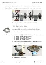
Place the halves of the hoist bracket (1) around the BRB Pneumatic/Auto
housing and screw then together with M8 cylinder screws on both sides.
A cable can now be suspended in the lug of the hoist bracket.
11.3
Depth setting plate
This depth setting plate ensures repeatable machining, improving heat
exchanger and boiler applications. Depth settings can be easily adjusted.
The spacer is particularly suited for use with the BRB Pneumatic/Auto.
1. Loosen tool mounting plate. The removal procedure depends on the drive
variant, the clamping system and the mandrel:
for BRB 2 "standard" see chap. 8.4, p. 35.
for BRB 2 "NC" see chap. 8.5, p. 40.
for BRB 4 "standard" see chap. 9.4, p. 51.
for BRB 4 "NC" see chap. 9.5, p. 54.
2. Clamp spacer (1) with slightly loosened screw (2) via the drilling head (3).
3. When the spacer is flush, tighten the screw (2).
4. Reassemble tool mounting plate.
Mounting the
hoist bracket on
BRB Pneumatic/Auto
Mounting the spacer
1
1
1
3
2


