[REV. 20190510] OC_GF_RA_BA_790142765_00__INH-02_EN
Orbitalum Tools GmbH
D-78224 Singen www.orbitalum.com
79
GF 4, GF 6, RA 8, RA 12 (AVM/MVM)
Set-up and assembly
enGLISH
8.2
Mounting the line laser (only at GF 4 and GF 6 (AVM/MVM))
nOTe!
In order to protect the line laser against transportation damage it is supplied separately
at the GF 4 and GF 6 (AVM/MVM) and has to be mounted on the machine before
commissioning. We recommend dismantling the line laser before every transportation of the
machine.
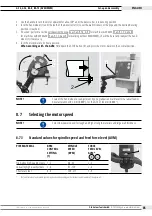
1. Take the Indicut line laser (1) out of the packaging and insert it together with the Plexiglas pane into the provided opening (2)
of the line laser holder at the machine.
2. Switch on the line laser and align it. The line of the laser has to be at a right angle to the pipe axis.
3. Carefully tighten the threaded pin M6x5 (3) (Code 445 001 210) of the line laser holder using an Allen key (Code 024 387 003).
2
1
3
8.3
Replacing the batteries of the line laser
ATTenTIOn!
It is not allowed to open, modify or to remove protective covers or housings except for
battery change. Observe the maintenance instructions (see chap. 10.1.1, page 99).
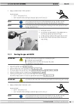
1. Loosen the threaded pin M6x5 (3) (Code 445 001 210) of the laser holder by using Allen key (Code 024 387 003) to remove the
laser from the cover plate.
2. Unscrew the line laser and replace the batteries (4) (Pack with 10 button cells, 1.5 V = Code 790 142 124).
3. Screw the parts of the line laser together.
4. Place the line laser back into the holder, align and retighten with the threaded pin M6x5 (3).
3
4
Summary of Contents for GF 4
Page 532: ......

