background image

20

Chapter 3

Facility Physical Requirements

 Figure 3.3  System Dimensions–Side View 

Summary of Contents for DP-100SL

Page 1: ...DP 100SL Site Preparation Guide October 2003 Revision A ...

Page 2: ......

Page 3: ...nd all implied warranties of fitness for particular purpose other than as specified in this manual are hereby expressly disclaimed This document is subject to change without notice Catalog No 0353444A Orbotech is a registered trademark of Orbotech Ltd The Orbotech and DP 100SL names are trademarks of LIS GmbH and Orbotech Ltd Other brand and product names referred to herein are the trademarks of t...

Page 4: ...Systems GmbH Co KG Prüssingstraße 41 07745 Jena Germany and by Orbotech Ltd P O Box 215 Yavne Israel 81002 The system complies with the following standards EN 60825 EN 60204 21 CFR CH I 4 1 92 EDITION 1040 10 The DP 100SL system is a Class 1 laser product ...

Page 5: ... 2 DP 100SL Physical Description 9 Configuration 9 Size and Weight 10 Hose Lengths 11 3 Facility Physical Requirements 13 Safety Requirements 13 Height Requirements 15 Floor Area 16 Access Doors and Hallways 17 Floors Walls Ceilings and Furniture 17 Yellow Room Illumination 18 4 Environment Climate 23 Clean Room 23 Climate Control 23 5 Electricity 27 Power Requirements 27 Grounding 28 ...

Page 6: ... 7 Communication 33 Phone Lines 33 Network 33 8 Air 35 Compressed Air 35 9 Shipment and Delivery 37 Shipping Information and Responsibility 37 Crates 37 Equipment 38 Personnel 38 Clearances 38 A Approved Materials 39 Dry Film Resists 39 Films 41 Proof Materials 41 B Customer Site Preparation Checklist 43 ...

Page 7: ...ed in this document so as to enable proper system installation and full system performance Please contact the local Orbotech representative with any questions regarding the site preparation procedure About the DP 100SL The DP 100SL is a laser direct imaging system that receives PCB data from CAM workstations and plots it directly on resist coated panels Loading and unloading of the PCBs is done ma...

Page 8: ...ompatible with the existing production processes operating in a yellow room environment it can expose all UV sensitive dry or liquid resists with a wide range of substrate thicknesses Clean room conditions prevail in the internal imaging area of the system ensuring that both the panels and the optical elements are not contaminated during the printing process Figure 1 1 DP 100SL Laser Direct Imagin...

Page 9: ...used in any way other than specified in this manual or in the DP 100SL User Guide Safety Considerations The DP 100SL is a Class 1 laser product containing high voltage power supplies and laser light sources There is no danger to persons or equipment when the system is operated in accordance with the directions provided by Orbotech in this and other publications All high voltage power supplies and ...

Page 10: ...em units is listed in Table 2 1 on page 10 System installation disassembly maintenance and repair must be performed only by authorizes Orbotech customer support engineers in order to comply with all applicable safety requirements regarding the use of laser devices Laser Safety The DP 100SL system is classified as a Class 1 laser product in compliance with EN60825 1 standard Laser Definition A Cohe...

Page 11: ...ice procedures Class 4 will be reached and therefore a warning light must be installed see Chapter 3 Main Wavelength 355nm 350 360nm UV light quasi cw power of 10W Secondary Wavelengths 1064nm 1060 1070nm UV light quasi cw power less 0 2W 532nm 520 540nm green light quasi cw power less 0 2W Minimal Beam Diameter 0 05 mm Minimal Beam Divergence 0 5 Pulse Rate 80MHz Pulse Energy 125nJ Pulse Length 5...

Page 12: ...y training to all employees who work on or around the laser system so that these employees understand the bio effects of lasers and laser radiation Full eye protection by safety goggles is required when machine is open during service maintenance i e laser reaches Class 4 in compliance with standard DIN EN207 See Safety Goggles on page 14 Fire Equipment Portable fire extinguishers must be on hand a...

Page 13: ...ls have a load capacity of up to 10 kg designed for carrying necessary work materials Do not place any objects on the movable cover plates Leaning sitting or stepping on the system is strictly forbidden The machine must not be used in any way other than specified in this manual or in the DP 100SL User Guide Noise Level The system s noise level is 70 dB A The noise level of the vacuum pump installe...

Page 14: ......

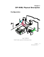
Page 15: ...2 DP 100SL Physical Description Configuration The DP 100SL comprises the following main units Figure 2 1 DP 100SL Site DP 100SL PLANT AIR 40µ 5µ FILTERED AIR TEL N W MAIN POWER SUN W S e N W TEL LASER SUPPLY BOX CONTROL BOX PUMP HOSE CABLE N W ...

Page 16: ...ard 209E Size and Weight Table 2 1 lists weight and size information for the standard DP 100SL units Table 2 1 Size and Weight of Standard DP 100SL Units ready for operation Unit Width Depth Height Weight DP 100SL Imager i e basic unit 1654 mm 65 12 in 2644 mm 104 09 in 1755 mm 69 11 in 2000 kg 4409 lbs Laser Supply Box attached to basic unit 1100 mm 43 31 in 810 mm 31 89 in 510 mm 20 08in 100 kg ...

Page 17: ... The customer must supply this table Sun workstation measurements are liable to change without notice Hose Lengths Table 2 2 lists information on the size of the hose s Table 2 2 DP 100SL Hose Lengths Hose Length standard supplied Diameter Compressed air line from the machine to plant air supply 10 m 33 ft 0 39 10 mm outside Note For vacuum pump hoses lines refer to Table 6 1 Vacuum Line Lengths o...

Page 18: ......

Page 19: ...ess to the Imager Room during Service The imager room door should have a lock that can be locked from the inside to prevent access to the room A box with a key to be used for entry in case of emergency should be located next to the door on the outside Note The customer is responsible for ensuring conformance with local safety regulations As such the requirements below can only be considered to be ...

Page 20: ... be available to completely isolate the unit from the rest of the room during servicing procedures example relevant laser safety curtains External Warning Light A red warning light should be placed on the outside of the imager room above the entrance The light will be activated under certain service conditions when the laser is on the hood up and the imager safety interlock neutralized The DP 100S...

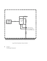
Page 21: ...stallation the machine height may vary within a vertical range of approx 80 mm 3 15 Achievable height levels are Between 964 mm 37 9 and 1044 mm 41 1 for the machine table Between 1021 mm 40 2 and 1101 mm 43 4 for the upper edge of the machine shielding mouse and keyboard placement level Figure 3 1 External Warning Light Supply Relay 24 V AC DP 100SL Laser Warning Lamp Max 500mA ...

Page 22: ...uired as work and maintenance areas for each unit is shown in Figure 3 4 on page 21 Operator s Working Area The user determines the floor space required for the operator Refer to Figure 3 4 on page 21 for dimensions of the recommended working area Pump Room The pump room requires a minimum floor space of 500 x 1000 mm 19 7 x 39 4 in Other Storage Storage shelves and cabinets as well as filing cabi...

Page 23: ...stem which weighs approximately 4409 lb 2000 kg Floor strength of 1800 Kg m is required as contact areas between system legs and the floor are small The floor supporting the DP 100SL must be level with a maximum permissible incline of 5 mm per 1 m 1 per 16 ft Ground floor location is recommended The system should not be located near heavy machinery that causes high shock or vibration levels Maximu...

Page 24: ...niture should be resistant to static buildup Cloth covered seats are preferable to plastic ones The feet of the furniture should not be insulated from the ground for example by rubber caps Yellow Room Illumination Safe lighting should be as per specifications of the resist manufacturer DuPont for example recommends Encapsulite Gold 10 Normal illumination should also be provided for maintenance and...

Page 25: ...DP 100SL 19 Site Preparation Guide Figure 3 2 System Dimensions Front View ...

Page 26: ...20 Chapter 3 Facility Physical Requirements Figure 3 3 System Dimensions Side View ...

Page 27: ...DP 100SL 21 Site Preparation Guide Figure 3 4 Site Dimensions Standard Configuration ...

Page 28: ...Requirements Figure 3 5 Mount Description for Vacuum Control Box 11 81 in 300 mm 1000 mm 39 4 in 400 mm 15 75 in Control Box Power Supply 3 Phase 200 400 VAC 50 60 Hz To Vacuum Pump 3m Control Signal 24V From DP 100SL System External ...

Page 29: ... with the following conditions Ceiling to floor laminar filtered airflow to reduce particulate contamination Class 10K clean room per Fed Spec 209E Inline active carbon filtration system Dedicated standalone air makeup system that is free from organic chemicals and ammonia that may attack system components Climate Control Room climate control must be designed so that operating temperatures and hum...

Page 30: ...m should not exceed 35 ºC Caution The air flow should not be directed toward the machine Table 4 1 Operating and Storage Temperatures Unit Operating Temperature Storage Temperature DP 100SL 20 C to 23 C 68 F to 73 F 0 C to 35 C 32 F to 95 F Caution In order to achieve the specified system performance the imager room temperature must be set within the above range and must not fluctuate more than 2 ...

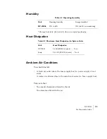
Page 31: ...y heat sink A warm air exhaust close to the main heat source i e laser supply box Take note that No organic chemicals allowed in the air No ammonia allowed in the air Table 4 2 Operating Humidity Unit Operating Humidity Storage Humidity DP 100SL 50 to 60 10 to 80 non condensing Table 4 3 Maximum Heat Dissipation for System Units Unit Heat Dissipation DP 100SL 5 kW 228 BTU minute To air Pump 2 5 kW...

Page 32: ......

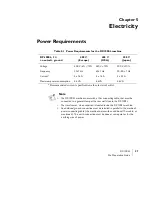
Page 33: ...rent 3 x 16 A 3 x 16 A 3 x 32 A Maximum power consumption 6 kVA 6 kVA 6 kVA Note The DP 100SL machine comes with a 10m connecting cable that must be connected to a general clamp at the rear wall close to the DP 100SL The transformer when required is located inside the DP 100SL machine An additional ground connection must be installed in parallel to the machine s power connecting cable the machine ...

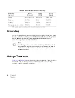
Page 34: ...e should be tested when all machinery and air conditioning units are operating normally and the system is turned on Table 5 2 Power Requirements for the Pump Pump 3 Φ ground 400 V Europe 208 V USA 200 V Japan Voltage 400 V 6 10 208 V 10 200 V 10 Frequency 50 1 Hz 60 Hz 50 60 Hz Current 3 x 16 A 3 x 16 A 3 x 16 A Maximum power consumption 2 5 kVA 2 5 kVA 2 5 kVA Note An additional ground connection...

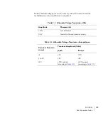
Page 35: ...s required Table 5 3 Allowable Voltage Transients USA Amplitude Measured At 10 Hot to Neutral 0 5 V Neutral to Ground common mode Table 5 4 Allowable Voltage Transients Europe Japan Transient Duration msec Transient Amplitude Volts Japan Europe 5 55 110 5 to 50 25 50 50 10 nominal according to Table 5 1 10 nominal according to Table 5 1 ...

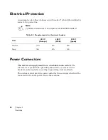
Page 36: ...esponsible for providing this switch as well as circuit breakers and receptacles according to prevailing local standards The customer must provide a power outlet for the servicing which will be connected to the same power line as the machine Note Release characteristic C in compliance with EN 60898 standard Table 5 5 Requirements for the circuit breaker Unit 400 V Europe 480 V USA 200 V Japan Mach...

Page 37: ...dB A Smooth plastic water installation piping is recommended Vacuum line lengths are specified in Table 6 1 below Pipe routing should enable access to all connection points for maintenance in case of leakage Note Important ensure this separate room is ventilated Table 6 1 Vacuum Line Lengths Hose Line Max Length Diameter Pump to DP 100SL vacuum line 40 m 132 ft 4 in Smooth plastic water installati...

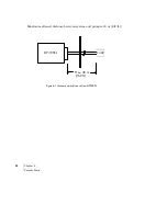
Page 38: ...32 Chapter 6 Vacuum Pump Maximum allowed distance between system and pump is 40 m 132 ft Figure 6 1 Vacuum pump distance from DP 100SL Max 40 m 132 ft PUMP DP 100SL ...

Page 39: ...ech personnel The customer will supply the telephone A second line should be available for remote diagnostics via modem Both lines should have direct outside dialing Network The customer is responsible for preparing four Ethernet network connection points in the immediate vicinity of the system The connecting points are required for DP 100SL basic unit CCD computer SUN workstation Service ...

Page 40: ......

Page 41: ...e customer s responsibility to maintain filtering of the outside supply to ensure an oil free compressed air supply Table 8 1 Compressed Air Requirements Pressure 0 7 1 0 MPa 7 10 bar Air supply rate 55 liters minute Quality Dry water 0 03 g m Filtered dust 0 1 µm 0 1 mg m Free of oil oil 0 01 mg m Tube connectors 10 mm outside diameter ...

Page 42: ... causing malfunction or damage A filtration system similar to the one in Figure 8 1 is recommended Figure 8 1 Recommended Air Filtration System 5m filter FESTO LFMB 1 2 D MIDI A or equivalent 40m filter FESTO LF 1 2 D MIDI A or equivalent Regulator with Pressure Gage FESTO LR 1 2 D MIDI or equivalent ...

Page 43: ...gineers will advise and instruct the customer on site preparation Crates The DP 100SL arrives in three wooden crates Crates approximate sizes and weights are given in Table 9 1 below Caution Equipment should be unpacked by authorized Orbotech engineers only Table 9 1 Shipping Crate Sizes Unit Width Depth Height Weight DP 100SLa a Includes the Laser Head 1920 mm 75 6 in 3020 mm 118 8 in 1990 mm 78 ...

Page 44: ...ional riggers to unload the crates and transfer them to the site The riggers will assist Orbotech personnel in unpacking the equipment No equipment should be unpacked before the arrival of Orbotech personnel Clearances Check crate delivery routes and remove all obstructions Ensure that all doors and hallways along the delivery route are large enough to provide sufficient clearance that elevators i...

Page 45: ...set the system up according to your working environment If you select alternative materials for exposure you must obtain prior approval of such materials from Orbotech Dry Film Resists Note Refer to Orbotech s CSE for latest Approved Materials lists Table A 1 List of Approved Dry Film Resists Type Manufacturer Approved for UV Marker Riston LDI 330 DuPont Riston LDI 350 Laminar 2000 UD 720 Shipley ...

Page 46: ...dyl alpha 450 Photec SL 1030 Hitachi Photec SL 1040 Photec HN 240 Photec HN 340 Photec HW 340 LDI 1000 TAIYO INK DiaEtch 320 HTP Probimage 1020 Vantico SUNFORT AQ 2058 Asahi SUNFORT AQ 3058 Imageline XV750 Coates Imagecure XV501T 4 ETERTEC LI 7000 Eternal ETERTEC LI 7100 Table A 1 List of Approved Dry Film Resists Type Manufacturer Approved for UV Marker ...

Page 47: ...A 2 List of Approved Films Type Manufacturer CU4 Kodak Contact 2000 Kodak CA4 Kodak Contact 2000 Kodak DC7 day light film Agfa Table A 3 List of Approved Proof Materials Type Manufacturer Dylux paper 535 1 DuPont Dylux paper 503 1 DuPont LCF Laser Check Film DuPont ...

Page 48: ......
Page 49: ... entrance Portable carbon dioxide fire extinguishers near the system Imager room has fireproof walls and furniture Protective goggles available in imager room Compressed Air Issues Complete Pending Date Notes Air line pressure 0 7 1 0 MPa 7 10 bar Air supply rate of 55 liters minute Quality dry water 0 03 g m filtered dust 0 1µm 0 1 mg m free of oil oil 0 01 mg m 10 mm φ tube connectors ...

Page 50: ...ilding ground Ground connection impedance less than 0 5 Ohms Electrical power for air conditioning is from different source than the system Requirements for the Pump as listed in Table 5 2 on page 28 Imaging Room Issues Complete Pending Date Notes Image room size at least 3 57W x 5 30L x 2 80H meters 11 7W x 17 4L x 9 2H feet The door is at least 1800 mm 71 wide and 2010 mm 79 high Room isolated t...

Page 51: ...ated near heavy machinery The amplitude of movement of vibrations must be less than 1 5 µm at 2 9 Hz The amplitude of acceleration of vibrations is less than 5 m s at 9 200 Hz Floor strength is at least 1800 kg m Floor incline no more than 5 mm per meter 1 per 16 ft The floor is covered with anti static tile rubber or linoleum No carpeting The Imaging room is its own room with its own environment ...

Page 52: ...e in original packing 32 F 95 F 0 C 35 C Temperature sensors installed in room Room humidity with machine in operation 50 60 Room humidity with machine in original packing 10 80 non condensing Humidity sensors installed in room Ventilation ceiling to floor or walls to floor filtered laminar airflow Pump Room Environment Issues Complete Pending Date Notes Room temperature max 35 C Furniture Issues ...

Page 53: ...llways to the imaging room from the storage room Unpacking space outside the work area Forklift and crane available for movement and installation Communications Issues Complete Pending Date Notes Four ethernet network connection points are available near the system A phone line with IDD is installed near the system A second phone line with IDD is installed for remote diagnostics via modem Sun Work...

Page 54: ...ative ________________ Date _______________ Material Issues Complete Pending Date Notes Proof Paper Antifoam according to the LDI producer Small pump to add antifoam into the developer LDI photoresist 6 liters of steam distilled water Table tooling hole dimensions were sent to Orbotech for OK LDI resist passed successfully all the processing tests including contact printing ...

Reviews: