background image

User manual


ZEUS


3


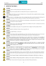
IMPORTANT WARNINGS 


WARNING! 

The unit can only be used for purposes prescribed by the manufacturer.


WARNING! 

Only an adult person acquainted with the content of this manual, can operate the device. 


DANGER! 

Unit Installation, first start-up, service and maintenance must be performed by a qualified installer and always 

in non-electrically supplied condition.


NOTE 

Install the device in a room/place, where there is enough space left around the device for cleaning and 

maintenance purposes. Consider the space for installation (recommended space requirements). 


DANGER! 

Never incline the device for more than 30°from its vertical position or transport/carry it by hand. To move the 

device, use only proper transport equipment.


WARNING! 

Do not install the unit in a space where the temperature can fall below 0°C, water in the pipes and unit can 

freeze and cause damage to the unit or pipes.


WARNING! 

The unit must be installed in a dry space, if it is exposed to direct sunlight, it must be protected from it.


DANGER! 

During operation it is forbidden to move, clean or repair the unit.


DANGER! 

Do not put any object below or on the unit.


WARNING! 

Connect the unit to the system using removable pipe unions, so that the unit can be easily moved or removed 

in case of a service intervention without the need of a greater intervention in the piping system.


DANGER! 

If the intended installation location of heat pump is in room, where there is a lot of dust or ash, possibility of 

leakage of volatile and flammable or other undesirable substances, wood or pellet stove, it is required to 

ensure air intake for the heat pump from another room. Ash and dust are deposited on the evaporator, which 

can lead to disturbances in operation or damage to the heat pump. 


DANGER! 

Non-return valve and dirt trap are necessary to install on the inlet tube. Also, it is necessary to install 

appropriate expansion vessel. It is 

MANDATORY

 to install safety valve (0,6 MPa) on the hot water outlet tube. 

Maximum allowed supply pressure is 0,4 MPa. 


WARNING! 

When connecting the unit to the heating system it is necessary to prevent the formation of a galvanic couple 

and related corrosion. To connect the unit to the heating system it is 

MANDATORY

  to use the enclosed 

transition pieces, also the piping system 

MUST

 be electrically grounded. In case of failure due to improper 

device connection the manufacturer will take no liability or warranty.


DANGER! 

In case of power supply cable damage, smoke, unusual smell from unit or any other abnormality in operation, 

immediately disconnect the power supply cable from the supply and contact an authorized customer service.


DANGER! 

Do not insert your fingers through the intake/exhaust gratings. Rotating parts of the device can injure you. 


DANGER! 

The unit requires reliable grounding during operation, otherwise serious injuries or even death may occur. 


DANGER! 

The unit needs to be connected to the power supply protected with the prescribed fuse. 

Summary of Contents for ZEUS ZSW 230

Page 1: ...I INSTALLATION MAINTENANCE AND USER MANUAL Domestic hot water heat pump ORCA ZEUS ZSW 230 and ZSW 300 V1_2022 ...

Page 2: ...nical or any other specifications without notice and without liability We do not take responsibility for typographical errors This work is copyrighted Any use outside the boundaries of the copyright law without the consent of Orca Energija d o o is illegal and punishable by law With this release all previous versions are invalid liability We do not take responsibility for typographical errors ...

Page 3: ...firmation before trial operation 14 14 UNIT SETTINGS 15 15 OPERATION INSTRUCTIONS 15 15 1 Function of wire controller 15 15 2 Operations 16 15 3 Turn ON OFF the unit 17 15 4 Mode selection 18 15 5 Time setting 19 15 6 In the vacation mode 23 15 7 Electric heater setting 24 15 8 Fan mode setting 24 15 9 Keyboard locking 25 16 PCB BOARD CONNECTIONS 26 17 TROUBLESHOOTING 26 18 ELECTRIC SCHEME 27 27 1...

Page 4: ...urer reserves the right to modify the installation maintenance and user manual without prior notice If you lose or damage the manual in unreadable condition contact the manufacturer or the retailer where you purchased the device 2 SAFETY WARNINGS Read the instructions bellow carefully In order to avoid any damage to persons animals or plants use the device only in accordance with the instructions ...

Page 5: ... installation location of heat pump is in room where there is a lot of dust or ash possibility of leakage of volatile and flammable or other undesirable substances wood or pellet stove it is required to ensure air intake for the heat pump from another room Ash and dust are deposited on the evaporator which can lead to disturbances in operation or damage to the heat pump DANGER Non return valve and...

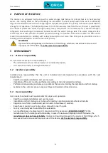
Page 6: ...ure above 50 C can cause injuries when set temperature is higher than 50 C be careful when children and other users are using hot water DANGER Evaporator operates at low temperature Touching it can cause frostbite DANGER Never damage or rupture the refrigerant piping Refrigerant leakage can cause serious frostbite DISPOSAL INSTRUCTIONS The unit must be replaced and disposed according to local regu...

Page 7: ...sponsibility if The installation and user manuals were not considered properly Unit was not correctly or enough maintained 5 2 Installer responsibility Installers take responsibility that the unit is installed and commissioned in accordance with the next requirements Read the complete installation and user manuals Installation of the unit must be performed according to national standards and laws ...

Page 8: ...ufacturer s refrigerant safety sheet and handle in accordance with the written instructions DANGER Refrigerant leakage can cause serious frostbite In case of refrigerant leakage immediately disconnect power supply and inform the authorized customer service Do not approach the device only when necessary to disconnect the power supply 7 RECYCLING 1 Waste Product Consult the manufacturer regarding re...

Page 9: ...on IPX IPX2 IPX2 IPX2 IPX2 IPX2 Refrigerant quantity Typ g R134a 1000 R134a 1000 R134a 1000 R134a 1000 R134a 1000 Tank volume L 230 230 300 300 300 Surface of bottom heat exchanger m2 0 5 1 1 Surface of upper heat exchanger optional m2 0 5 Air flow m3 h 500 500 500 500 500 Air connection dimensions mm 150 150 150 150 150 Maximal length of air ducts m 10 10 10 10 10 Unit dimensions D x H mm 670 x 1...

Page 10: ...tective foil or cardboard to avoid damage such as scrapes abrasions and holes WARNING Because of the device s construction the aggregate being on top there is a high risk of the device overturning during transport The max incline of 30 must not be exceeded WARNING Do not exceed the maximum inclination of 30 from vertical WARNING The allowed temperature during transport and depot is between 10 and ...

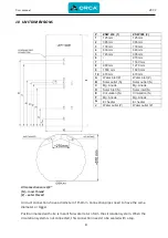
Page 11: ... Solar inlet N Solar inlet N E Circulation N Circulation N F Mg Anode Mg Anode G El heater El heater J Water outlet Z Water outlet Z 10 UNIT DIMENSIONS All connections are 3 4 N inner thread Z outer thread Air duct connections have a diameter of 150mm Connection pipes need to have the same diameter or bigger Position marked with E is meant for water return form the circulation system When the circ...

Page 12: ...After placing the unit in its final location wait at least 1 hour before turning the unit on WARNING In case of service intervention and if minimum clearances are disregarded the user covers the costs incurred Min one elbow is required Because the inlet and outlet air connections are very close together there is a possibility of cold air recirculation the device will go to defrost mode more often ...

Page 13: ...th for 1 m All air duct pipes need to be insulated to prevent condensation Never reduce the internal diameter of the pipe When the air inlet and outlet are in a different space each space needs to have an opening to the outside or they need to be connected with an opening surface at least 300mm2 to be able to equalize pressure ...

Page 14: ...s not allowed to close both sides of the heat exchanger to enable pressure equalization WARNING Improper installation of the unit can lead to damages or malfunction of the unit and loss of rights under warranty WARNING Connect the unit to the system using removable pipe unions so that the unit can be easily moved or removed in case of a service intervention without the need of a greater interventi...

Page 15: ...ocket must be earthed secured with a 16A fuse and FI relay with max current 0 03A The wire cable to the socket needs to be at least 3x2 5 mm only the heat pump can be connected to the socket 12 1 Galvanic cell DANGER Prevent corrosion due to formation of a galvanic couple the heat pump must be properly connected to the system Fittings are enclosed with the heat pump to connect the cold and hot wat...

Page 16: ...CAUTION Before using this unit please follow the steps below Adding water If the unit is used for the first time or used again after emptying the tank please make sure that the tank is full of water before turning the power on NOTE The ball valve at water inlet should be open when the unit is in operation WARNING Operation without water in the water tank may result in damage of auxiliary electrica...

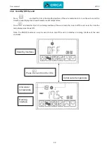
Page 17: ...50 Hz 15 OPERATION INSTRUCTIONS 15 1 Function of wire controller No Button Name Function 1 ON OFF Turn on off the unit 2 Mode Switch unit running modes or save setting parameters 3 Clock Set the clock or the timer 4 Electric heater Turn on off the electric heater or switch fan modes 5 Up Move up or increase parameter values 6 Down Move down or decrease parameter values Auxiliary display area Main ...

Page 18: ... the water temperature has reached the target point and the unit shuts off automatically Parameter setting Shows that the water temperature has reached the target point and the unit shuts off automatically Temperature Shows that the temperature is non adjustable measured value Timer ON Shows that the unit will be turned on by the timer automatically Timer OFF Shows that the unit will be turned off...

Page 19: ...let temperature Press and hold for 0 5s in the running interface of the wire controller to turn off the unit an at this time the main display area shows OFF Note The ON OFF button can only be used to turn on off the unit in standby or running interface of the wire controller Heating mode Press and hold for 0 5s Standby interface Outlet water temperature Inlet water temperature Running interface ...

Page 20: ...rature After making the changes to the parameter press to confirm or cancel the changes then return to the previous interface If no operations are performed on the keypad for 0 5s the controller exits the parameter modification menu by time out and the changes are confirmed Example Change the target temperature from 50 to 55 5 when the actual outlet water temperature is 18 C Outlet water temperatu...

Page 21: ...o change it After making the changes to the parameter press to confirm then change the minute parameter as well as the date parameter in the same way If no operations are performed on the kaypad for 10s the controller exits the parameter modification menu by timeout and the changes are confirmed Note Set the data in the same way when in vacation mode Example Change the time and date from 18 30 on ...

Page 22: ...ding to the 2 6 and confirm Then OFF 1 and the time parameter flashes Set the time following the previous steps Running period 2 After Running Period 1 is set the controller will enter into the Running period 2 setting interface Set the start up and shut down time in the same way as Running period 1 Press to cancel any modifications during the setting Press and hold for 2s twice to set the OFF 1 t...

Page 23: ...User manual ZEUS 21 Example Running period 1 8 00 10 00 Running period 2 16 30 22 00 ...

Page 24: ...User manual ZEUS 22 If you want to cancel the timer setting follow the instruction listed below ...

Page 25: ...ss and hold for 2s to enter into the timer setting interface The symbol ON and the data parameter are flashing at this time Then set the date in the same way as 2 6 Note Turn off the unit before going out Example Set the start up date on September 28 ...

Page 26: ... mode to high speed running and the fan will run at high speed when the unit target temperature is reached Press and hold for 2s for the third time to change the fan mode to shut down and the fan will stop running when the unit target temperature is reached Definition of the fan icon 1 Running shows that the fan is running at hight speed 2 Running shows that the fan is running at low speed 3 Fan i...

Page 27: ...apest if it will not always need to heat to the maximum permissible temperature of the water in the reservoir The lower the temperature in water container is set the lower the costs for water heating will be Therefore it is recommended to set parameter r01 somewhat lower than factory setting eg to 45 C and allow disinfection mode to heat the water to 60 C once per month using the electrical heater...

Page 28: ...ck or change the pipe temp sensor P07 Suction sensor failure The temp sensor is open or short circuit Check or change the suction temp sensor P09 Coolant sensor The temp sensor is open or short circuit Check or change the coolant temp sensor E01 High pressure protection The exhaust pressure is high high pressure switch action Check high pressure switch and system circuit E02 Low pressure protectio...

Page 29: ...GND SUT 5K OUT3 OUT1 AI06 SUT 5K 7 AI04 GND GND CT CT AC N GND BTT BLU zz GND AT AT L N 12 HP TO POWER SUPPLY AT Ambient temperature COMP Compressor FM Fan motor SUT Suction temperature TC Transformer 4V 4 way valve 18 ELECTRIC SCHEME ...

Page 30: ...User manual ZEUS 28 18 1 Temperature sensor resistance ...

Page 31: ...User manual ZEUS 29 19 UNIT COMPONENTS 18 UNIT COMPONENTS ...

Page 32: ...et pipe 13 Gas outlet pipe 14 4 way valve 15 Compressor holder 16 Strengthen holder 17 Compressor rubber dampers 18 Compressor plate 19 Condensate plate 20 PCB cover 21 Main cover 22 Centrifugal fan with motor 23 Evaporator holder 24 Fan holder 25 Compressor capacitor 26 Expansion valve 27 Compressor 28 Compressor holder 29 Evaporator High pressure switch Low pressure switch Temp sensor all Power ...

Page 33: ... unwanted substances wood or pellet stove arrange heat pump air intake from another room Dust and ash are deposited on heat pump evaporator and inside the heat pump which can lead to operation disruptions or heat pump malfunctions Leakeage of explosive substances can lead to explosion or fire WARNING Periodically every 6 months check the connections power water refrigerant to the heat pump Pay att...

Page 34: ... and device inspection Electrical heater inspection Operation control of electronic elements compressor ventilator circulating pump overflow valve diverter valve Additional training of the user to ensure smooth operation of the device 20 3 Malfunctions and resolutions Malfunctions Causes Resolutions Units doesn t work 1 Power supply failure 2 Power supply connection failure 3 Power supply fuse fai...

Page 35: ...alvanic couple formation prevention were followed This warranty does not apply in the following cases Unit was not used in accordance with enclosed manuals Installation and or first start of unit was not performed by authorized person Repairs were performed by non authorized person Negligent handling with device Damage caused by mechanical shock from buyer or a third party If during the warranty p...

Page 36: ...or Slovenija INSTALLER installer fills out STAMP ___________________________________________ Company name ___________________________________________ Company address Date of installation _____________________________ List of authorised service technicians installers in Slovenia ORCA ENERGIJA d o o Vodovodna ulica 30c 2000 Maribor Tel 05 90 75 005 ...

Reviews: