


12
Fitting and maintenance instructions HRC 300/400 4B(P/RH)
4.3 Mounting of the heat-exchanger and the motor plates
•
Replace the heat exchanger and fans by reversing the
instructions in 4.2
•
Replace the heat exchanger from above and ensure that there
is no leakage between supply and extract airflows.
•
Push the pressure tray into position. This may require some
force as the seal between the exchanger and the housing is
a tight fit. Replace the filters.
•
Replace the motor plates into the housing and fix the 4 screws.
Reconnect the wiring of the motor to the motor-pcb.
•
Mount the cover of the unit.
•
Reconnect the power to the unit and check that the unit
functions correctly.
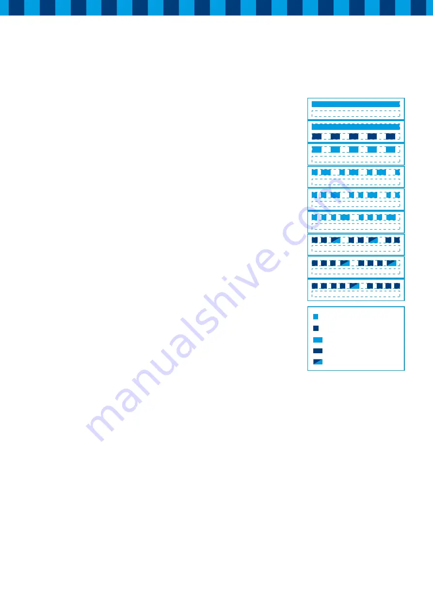
4.4 LED indication / Fault warnings
When there is a failure or a certain scenario, this will be shown
on the display of the unit. The key to the meanings of the various
LED indications is located on the filter door of the cover. A red
LED indicates that action is required. A green LED indicates a
particular mode of operation. When the LED indication is not
in the key shown here stop the unit immediately and contact
your installer or the distributor of the unit.
Meaning LED-signs
Normal function
Filter polluted
Frost
Defrost-cycle
Moist detected
Summer/Comforttemp.
Failure Bypass valve
Failure temperature sensor
Failure moist sensor
= Green, short
= Red, short
= Green, long
= Red, long
= Red or green, long


