


15
Fitting and maintenance instructions HRC 300/400 4B(P/RH)
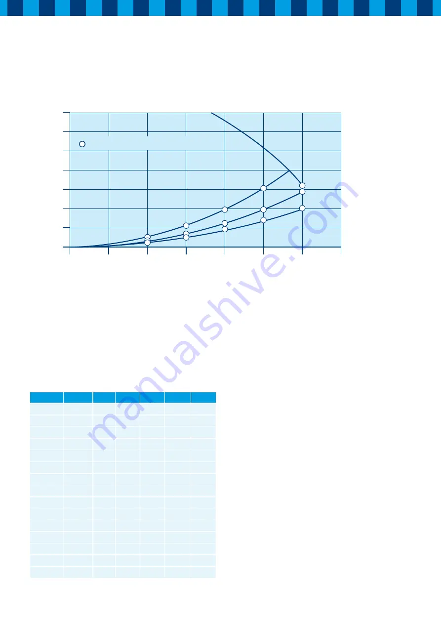
5.3 Fan graph HRC 300 4B(P/RH)
Point
[m3/h]
[Pa]
U [V]
I [A]
cos
ϕ
P [W]
A
100
12
230
0,068 0,602
9,4
B
100
16
230
0,070 0,604
9,7
C
100
25
230
0,075 0,612
10,6
D
150
25
230
0,102
0,626
14,8
E
150
36
230
0,110
0,621
15,7
F
150
56
230
0,120
0,625
17,3
G
200
44
230
0,188
0,643
27,8
H
200
64
230
0,191
0,642
28,2
I
200
100
230
0,225 0,652
33,7
J
250
69
230
0,287 0,663
43,8
K
250
100
230
0,323 0,668
49,6
L
250
156
230
0,402 0,667
61,7
M
300
100
230
0,472 0,671
72,9
N
300
144
230
0,515
0,658
77,9
O
300
160
230
0,546 0,662
83,2
Resistance ducts system (P
a)
350
300
250
200
150
100
50
0
0
50
100
150
200
250
300
350
C
B
A
F
E
I
H
G
L
K
J
O
N
M
D
Power consumption per fan [w], see table
Airflow (m
3
/h)


