


17
Fitting and maintenance instructions HRC 300/400 4B(P/RH)
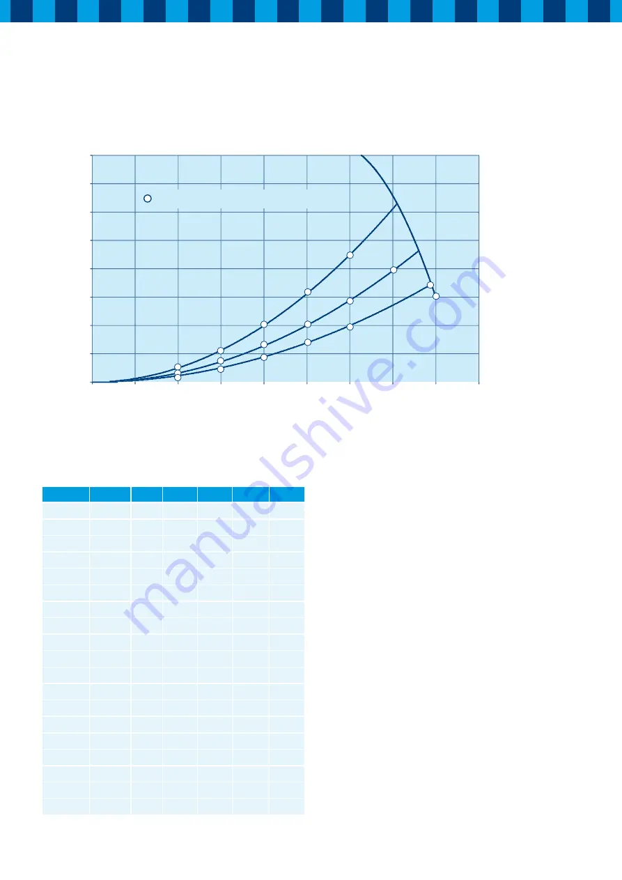
5.5 Fan graph HRC 400 4B(P/RH)
Point
[m
3
/h]
[Pa]
U [V]
I [A]
cos
ϕ
P [W]
A
100
12
230
0.080 0.509
9
B
100
16
230
0.083 0.511
10
C
100
25
230
0.088 0.519
11
D
150
25
230
0.120
0.533
15
E
150
36
230
0.129
0.528
16
F
150
56
230
0.141
0.532
17
G
200
44
230
0.220 0.550
28
H
200
64
230
0.223 0.549
28
I
200
100
230
0.262 0.559
34
J
250
69
230
0.334 0.570
44
K
250
100
230
0.375 0.575
50
L
250
156
230
0.467 0.574
62
M
300
100
230
0.548 0.578
73
N
300
144
230
0.600 0.565
78
O
300
225
230
0.790 0.580
105
P
350
140
230
0.820 0.640
121
Q
350
200
230
0.960 0.590
133
R
375
175
230
1.115
0.590
156
S
400
150
230
1.29
0.590
175
Airflow (m
3
/h)
Resistance ducts system (P
a)
0
50
100
150
200
250
300
350
400
0 50 100 150 200 250 300 350 400 450
D
E
F
I
H
G
J
M
N
O
Q
S
R
K
L
C
B
A
Power consumption per fan [w], see table


