background image

18

Fitting and maintenance instructions HRC 300/400 4B(P/RH)

5.6 Setting transmitter / receiver (RH model only)

When current is put on the device, the red LED is flashing 3x on 
the receiver print. 

Login for 1 remote.

Press the pushbutton on receiver print for 2 seconds. The red LED 
is flashing 2x, followed by continuously burning red LED.
On  the  remote,  press  [auto]  and  [key  1]  simultaneously.  Keep 
pressing until the green LED on the remote stays.
When the remote is logged in, the red LED on the receiver print is 
flashing 10x, then the green LED on the remote flashes 3x. Now 
the remote is ready for use.

Login of 2 remote controls.

Press the pushbutton on receiver print for 2 seconds. The red LED 
is flashing 2x and goes.
On  the  remote,  press  [auto]  and  [key  1]  simultaneously.  Keep 
pressing until the green LED on the remote goes.
When the remote is notified, the red LED on the receiver print is 
flashing 10x, thereupon the green LED on the remote is flashing 
3x. Now the remote is ready for use.

Remote 2 is logged in the same manner as remote 1.

When a third remote is notified, it will overwrite the second remo-
te. The first remote stays logged on.
To replace remote no. 1, it is necessary to erase the print of the 
home ventilator. Only then it is possible to notify a new remote(s).

Logout of the remote controls.

Press the pushbutton on receiver print continuously until the red 
LED goes. After releasing the button, the red LED on the receiver 
print will flash 5x. The link with the remote is now erased

Battery replacement.

When the LED indication on the remote does not react when one 
of the buttons on the remote is pushed, it is probably due to a 
low battery. To replace the battery, you do not need to contact 
your installer.
You can easily do it yourself. The battery is commercially availa-
ble (typ: 3V CR 2032).
To  replace  the  battery,  you  first  slide  the  remote  in  a  vertical 
upward direction in order to detach the remote from the holder. 
At the back of the remote, you find two screws, unscrew them. 
Now you can remove the back of the remote. Remove the old bat-
tery from the remote and replace it by a new one. Make sure the 
positive side/plus of the battery faces you. Replace the back of 
the remote and screw. Replace the remote in to the holder.

If there are still problems arising, please contact your installer.

Please do not mount the remote control under a metal cooker hood.

Mount on a flat surface with the screws and wall plugs supplied. 

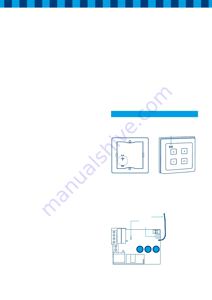
Figure 10: Battery replacement 

Figure 11: Remote control

Use

The remote control of the HRC is fitted with two keys:

•  

1 =  High: use this speed for cooking or showering

• 

2 =  Middle: for daily use by normal use of the dwelling

• 

3 =  Low: for use during the night or during vacations.

•  

AUT = Pressing this key, the unit works as Low.

Figure 12: Receiver print

3V CR2025

/ 3V CR2032

Green LED

ON

1  2 

Drukknop 


Rode Led


Antenne

Antenna
Red LED
Pushbutton

Summary of Contents for HRC 300 4B P

Page 1: ...overy unit www orcon nl Type HRC 300 400 4B P RH Store near the appliance This manual is intended for users and installers of type HRC 300 400 B P RH This manual contains impor tant about the operatio...

Page 2: ...arm damp and polluted air as near as possible to the source will be extracted The exhausted air must be replaced with fresh air and so the HRC heat recovery unit has not only an exhaust fan but is als...

Page 3: ...rom the house are attached to the other side of the unit Also the condensate discharge under the unit can be fitted at this stage B When the ducting runs are completed if an appropriate electrical sup...

Page 4: ...ere to fit the condensate discharge The position of the electrical power supply an earthed wall socket or fused switched spur is also indicated The unit must be secured horizontally Ensure sufficient...

Page 5: ...void in such a manner as to prevent condensation in addition the discharge duct between the HRC and the roof terminal must be designed to prevent surface condensation The mechanical ventilation outlet...

Page 6: ...the upper side of the cover at the upper side of the mounting frame with the two screws provided If it is difficult to push the cover totally against the unit open the flap in the cover After closing...

Page 7: ...the turn module are used to configure the unit for left or right handed operation and must not be changed or removed after the initial set up Attention Keep the magnet away from creditcards and other...

Page 8: ...7 OFF 8 ON 280 m3 h 5 OFF 6 ON 7 ON 8 ON 300 m3 h 5 ON 6 ON 7 OFF 8 ON 300 m3 h 1 ON 2 ON 100 m3 h 5 ON 6 OFF 7 OFF 8 OFF 210 m3 h 5 OFF 6 OFF 7 ON 8 OFF 225 m3 h 5 ON 6 ON 7 OFF 8 OFF 240 m3 h 5 OFF...

Page 9: ...OFF 6 ON 7 OFF 8 ON 345 m3 h 5 OFF 6 ON 7 ON 8 ON 370 m3 h 5 ON 6 ON 7 OFF 8 ON 390 m3 h 1 ON 2 ON 120 m3 h 5 ON 6 OFF 7 OFF 8 OFF 255 m3 h 5 OFF 6 OFF 7 ON 8 OFF 275 m3 h 5 ON 6 ON 7 OFF 8 OFF 295 m3...

Page 10: ...ll start flashing on off This filter indication will start flashing each month The unit should not be used without filters Cleaning the filters by user 4 Maintenance 4 After cleaning replace filters a...

Page 11: ...an the fan with a dry stiff brush Prevent damage to the fan blades Do not use water for cleaning 2 Clean the heat exchanger with warm water and a mild detergent Rinse with warm water 1 Switch off the...

Page 12: ...of the unit Reconnect the power to the unit and check that the unit functions correctly 4 4 LED indication Fault warnings When there is a failure or a certain scenario this will be shown on the displa...

Page 13: ...13 Fitting and maintenance instructions HRC 300 400 4B P RH 5 1 Wiring diagram Orcon HRC 300 400 4B P RH 5 Technical specifications...

Page 14: ...ternal diameter condensate discharge mm 20 Filter class G3 F7 optional Weight kg 39 kg frame 12 kg unit 23 kg cover 4 kg Supply voltage V Hz 230 50 Protection degree IP30 Temperature efficiency 95 Fac...

Page 15: ...150 56 230 0 120 0 625 17 3 G 200 44 230 0 188 0 643 27 8 H 200 64 230 0 191 0 642 28 2 I 200 100 230 0 225 0 652 33 7 J 250 69 230 0 287 0 663 43 8 K 250 100 230 0 323 0 668 49 6 L 250 156 230 0 402...

Page 16: ...m 210 Outside diameter ducts External diameter condensate discharge mm 20 Filter class G3 F7 optional Weight kg 39 kg frame 12 kg unit 23 kg cover 4 kg Supply voltage V Hz 230 50 Protection degree IP3...

Page 17: ...230 0 223 0 549 28 I 200 100 230 0 262 0 559 34 J 250 69 230 0 334 0 570 44 K 250 100 230 0 375 0 575 50 L 250 156 230 0 467 0 574 62 M 300 100 230 0 548 0 578 73 N 300 144 230 0 600 0 565 78 O 300 22...

Page 18: ...receiver print continuously until the red LED goes After releasing the button the red LED on the receiver print will flash 5x The link with the remote is now erased Battery replacement When the LED in...

Page 19: ...1 Profile 12 Bypass 13 Cover Article codes service articles HRC Nr Article description Article code S1 Central PCB Orcon 3 1 22905024 S2 Receiver pcb RH model only 29190742 S3 Filter set 2 x G3 filter...

Page 20: ...Storkstraat 23 3905 KX Veenendaal NL P o box 416 3900 AK Veenendaal t 31 0 318 54 47 00 f 31 0 318 54 47 06 info orcon nl Orcon bv www orcon nl Edition april 2010 29199185 orc10018...

Reviews: