5
Fitting and maintenance instructions HRC 300/400 4B(P/RH)
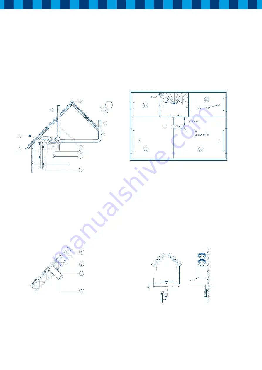
A
= No exhaust too close to an air inlet
B
= Ventilation inlet possible near roof end
C
= Inlet roof terminal
D
= Ventilated ridge tile
E
= Duct from and to outside - insulated
F
= HRC (horizontal position)
G
= Condensate discharge conforms to installation instructions
H
= Ducts from and to the dwelling acoustically insulated
I
= Ventilation exhaust roof terminal
Figure 2: Connection example HRC
Arrange the exterior air supply from the sheltered side of the
dwelling, for instance from the wall. Install the exterior air
supply duct in such a manner that surface condensation is
prevented.
A
= 10mm above roofing
B
= roof insulation
C
= insulated with PUR
D
= duct for air inlet - insulate carefully
Figure 3: Discharge duct through the roof.
Feed the discharge duct through the roof void in such a manner
as to prevent condensation; in addition, the discharge duct
between the HRC and the roof terminal must be designed to
prevent surface condensation.
The mechanical ventilation outlet, the air inlet and any soil &
vent pipes should each be separated by at least one meter.
A
= Outlet valve ø125 plastic (MKL) or metal (EFF-125)
B
= Inlet valve ø100 (TFF-100) or ø125 (TFF-125)
a
= Gap under the door 2 cm.
Figure 4: Location outlet and inlet valves
Install sufficient overflow openings, door gap 2 cm.
3.4 Connecting condensate discharge
The condensation-trap must be mounted at the bottom of the
HRC with the wire clip supplied.
Caution!
Before mounting you have to fill the trap with water.
The diameter of pipework to the air-trap is 32 or 40 mm. The
position of the drain is indicated at the drawing in the mounting
frame. The condensate water must leave through the drain
pipe. Take care that the distance between siphon and air-trap
will be enough for de-mounting and cleaning.
Figure 5: Connection of HRC to drain pipe