background image

7

Fitting and maintenance instructions HRC 300/400 4B(P/RH)

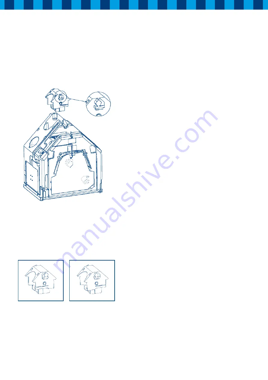
3.8 Overview connection HRC

The HRC can be configured either as a standard or a mirrored 
unit. As a standard unit, the duct connections on the left side 
of the unit will go outside and the duct connections at the right 
side go to the dwelling. The turn-module will show a “tree” on 
the left and a “house” on the right side.

Figure 8: Turn-module

If the unit is to be configured as a mirrored unit, you can pull 
the turn-module out of the unit and turn it 180° (reverse side 
to the front) and insert it b ack into position. You will see that 
now the “tree” is on the right side and the “house” on the left 
side. The connections at the unit have now changed. The
connections on the left side now lead to the dwelling and the 
connections on the right side lead outside.


Figure 9: Turn-module (detail)

The top connection is always the suction side (suction from 
outside or from the dwelling) and the bottom connections are the 
pressing connections (exhaust to outside or inlet to the dwelling).
The magnets on the turn-module are used to configure the unit 
for left or right-handed operation and must not be changed or 
removed after the initial set up. 

Attention!

 Keep the magnet away from creditcards and other 

objects sensitive to magnetic fields. 

3.9 Adjusting the air performance

The HRC is provided with constant volume fans. 
The integrated electronics controls the speed of each ventilator,  
to keep the airflow equal conform the settings of the dipswitches  
independent of the resistance of the system. For this reason 
the speed of both fans will not always be equal, because the 
resistance of the inlet and exhaust system will not always 
will be equal.
By means of the dip switches on motor-pcb’s at both sides of  
the unit, you can easily change the airflow of the highest speed. 

To change the airflow of the ventilator follow instructions 
below:

1.

  Remove the cover from the unit.

2.

  The dip switches on the motor-pcb’s on both sides of the unit 

are now accessible

3.

  Set the dip switches on both pcb’s to the desired airflow after 

checking the setting on the drawing below.

4.

  Refit the cover and make sure that the filters in the unit are 

clean.

5.

 Restart the unit.

Important:

  Before removing the cover you must disconnect the 

electrical power to the unit.

Summary of Contents for HRC 300 4B P

Page 1: ...overy unit www orcon nl Type HRC 300 400 4B P RH Store near the appliance This manual is intended for users and installers of type HRC 300 400 B P RH This manual contains impor tant about the operatio...

Page 2: ...arm damp and polluted air as near as possible to the source will be extracted The exhausted air must be replaced with fresh air and so the HRC heat recovery unit has not only an exhaust fan but is als...

Page 3: ...rom the house are attached to the other side of the unit Also the condensate discharge under the unit can be fitted at this stage B When the ducting runs are completed if an appropriate electrical sup...

Page 4: ...ere to fit the condensate discharge The position of the electrical power supply an earthed wall socket or fused switched spur is also indicated The unit must be secured horizontally Ensure sufficient...

Page 5: ...void in such a manner as to prevent condensation in addition the discharge duct between the HRC and the roof terminal must be designed to prevent surface condensation The mechanical ventilation outlet...

Page 6: ...the upper side of the cover at the upper side of the mounting frame with the two screws provided If it is difficult to push the cover totally against the unit open the flap in the cover After closing...

Page 7: ...the turn module are used to configure the unit for left or right handed operation and must not be changed or removed after the initial set up Attention Keep the magnet away from creditcards and other...

Page 8: ...7 OFF 8 ON 280 m3 h 5 OFF 6 ON 7 ON 8 ON 300 m3 h 5 ON 6 ON 7 OFF 8 ON 300 m3 h 1 ON 2 ON 100 m3 h 5 ON 6 OFF 7 OFF 8 OFF 210 m3 h 5 OFF 6 OFF 7 ON 8 OFF 225 m3 h 5 ON 6 ON 7 OFF 8 OFF 240 m3 h 5 OFF...

Page 9: ...OFF 6 ON 7 OFF 8 ON 345 m3 h 5 OFF 6 ON 7 ON 8 ON 370 m3 h 5 ON 6 ON 7 OFF 8 ON 390 m3 h 1 ON 2 ON 120 m3 h 5 ON 6 OFF 7 OFF 8 OFF 255 m3 h 5 OFF 6 OFF 7 ON 8 OFF 275 m3 h 5 ON 6 ON 7 OFF 8 OFF 295 m3...

Page 10: ...ll start flashing on off This filter indication will start flashing each month The unit should not be used without filters Cleaning the filters by user 4 Maintenance 4 After cleaning replace filters a...

Page 11: ...an the fan with a dry stiff brush Prevent damage to the fan blades Do not use water for cleaning 2 Clean the heat exchanger with warm water and a mild detergent Rinse with warm water 1 Switch off the...

Page 12: ...of the unit Reconnect the power to the unit and check that the unit functions correctly 4 4 LED indication Fault warnings When there is a failure or a certain scenario this will be shown on the displa...

Page 13: ...13 Fitting and maintenance instructions HRC 300 400 4B P RH 5 1 Wiring diagram Orcon HRC 300 400 4B P RH 5 Technical specifications...

Page 14: ...ternal diameter condensate discharge mm 20 Filter class G3 F7 optional Weight kg 39 kg frame 12 kg unit 23 kg cover 4 kg Supply voltage V Hz 230 50 Protection degree IP30 Temperature efficiency 95 Fac...

Page 15: ...150 56 230 0 120 0 625 17 3 G 200 44 230 0 188 0 643 27 8 H 200 64 230 0 191 0 642 28 2 I 200 100 230 0 225 0 652 33 7 J 250 69 230 0 287 0 663 43 8 K 250 100 230 0 323 0 668 49 6 L 250 156 230 0 402...

Page 16: ...m 210 Outside diameter ducts External diameter condensate discharge mm 20 Filter class G3 F7 optional Weight kg 39 kg frame 12 kg unit 23 kg cover 4 kg Supply voltage V Hz 230 50 Protection degree IP3...

Page 17: ...230 0 223 0 549 28 I 200 100 230 0 262 0 559 34 J 250 69 230 0 334 0 570 44 K 250 100 230 0 375 0 575 50 L 250 156 230 0 467 0 574 62 M 300 100 230 0 548 0 578 73 N 300 144 230 0 600 0 565 78 O 300 22...

Page 18: ...receiver print continuously until the red LED goes After releasing the button the red LED on the receiver print will flash 5x The link with the remote is now erased Battery replacement When the LED in...

Page 19: ...1 Profile 12 Bypass 13 Cover Article codes service articles HRC Nr Article description Article code S1 Central PCB Orcon 3 1 22905024 S2 Receiver pcb RH model only 29190742 S3 Filter set 2 x G3 filter...

Page 20: ...Storkstraat 23 3905 KX Veenendaal NL P o box 416 3900 AK Veenendaal t 31 0 318 54 47 00 f 31 0 318 54 47 06 info orcon nl Orcon bv www orcon nl Edition april 2010 29199185 orc10018...

Reviews: