14
8. Connecting accessories
All electrotechnical operations and connections must be carried out
according to and comply with the legal requirements.
Connecting the
CO2 sensor
(WTU-EC-E/IE/TA)
The units of the WTU-EC-E/IE series can be controlled by an air quality sensor. This can
be done via a
CO2 room sensor
or a
CO2 channel sensor
.
CO2 room sensor
Connect the 0-10V signal from the sensor (terminal 8) to terminal 2 of the WTU
terminal strip. Connect terminal 7 (GND) to terminal 3 (AGND) of the WTU terminal
strip.
Always use a separate switched-mode power supply for the room sensor.
(Article no: 17700120)
CO2 channel sensor
The
CO2 channel sensor
can be connected directly to the WTU terminal strip. Connect the
brown wire (0-10V) to terminal 2, the red wire (+24V) to terminal 5 and connect the
black wire (GND) to terminal 3 (AGND) of the WTU terminal strip.
After connecting the
CO2 sensor
, it must be configured in the controller (see page21).
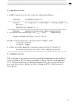
Connecting MTV-3 switch
The devices can be controlled by an MTV-3 switch by means of a 0-10V signal.
The MTV-3 can be connected to terminal 1 (+10 Volt), terminal 2 (0-10v) and with
terminal 3 (AGND).
After connection, the MTV-3 must be activated as
CO2
sensor in the controller
(see page 22).
Connecting CBA reheater to WTU-EC-E/IE/TA
The electric duct heater can be installed horizontally in any position except for the
position where the terminal box faces downwards. In case of a vertical installation, the
air flow should be directed upwards. When installing the CBA duct heater, observe the
minimum distance from the WTU
(at least 2x duct diameter). The temperature sensor should be mounted at a distance of at
least three times the duct diameter after the reheater.
Summary of Contents for WTU-1000-EC-E
Page 2: ...2...
Page 6: ...6 carried out...
Page 16: ...16 Note The connections shown in a box are optional Electrical Connections WTU EC E IE TA...
Page 41: ...40 Notes...


